In the recent years, the global energy demand has significantly increased due to the continuous increase in the world population and the rapid development in industry. Employment of alternative clean energy sources (i.e. solar, geothermal, biomass, etc.) and developing efficient energy conversion systems are among the prospective means to tackle the energy shortage problem and, at the same time, to mitigate the negative environmental impacts caused by the excessive consumption of fossil fuels [1], [2]. However, these energy sources are often available in the form of relatively low-temperature scales.
The use of conventional steam Rankine cycles to recover low-temperature heat sources, typically below 150 °C, is a challenging task. Such power systems are rather more suitable for high-temperature applications as water needs to be heated to as high as around 450 °C as a compromise between the high performance and technical limitations of the technology [3]. Power generation from low to medium temperature heat sources has technical and feasibility constraints, and only limited choices are available for low-temperature heat engines. Organic Rankine Cycles (ORC) and Kalina cycles have demonstrated their capability to efficiently harness such sources with an advantage going to the former due to their much less complexity and less maintenance needed [4].
Due to the use of organic fluids with low boiling temperatures as a working substance instead of water, the ORC is characterised by its ability to efficiently convert lower temperature heat into useful work more economically compared to the conventional steam Rankine cycle especially in the small scale applications ranging from few kW up to 1 MW [5], [6]. Furthermore, the broad variety of possible working fluids makes the ORC suitable for a wide range of heat sources. It should be mentioned that the selection of the most appropriate organic working fluid plays a vital role in determining the overall thermodynamic and economic system performance [7]. Therefore, the thermodynamic system performance, system cost, and safety and environmental requirements should be all considered in the working fluid selection stage.
The ORC technology is therefore technically suitable for heat to power conversion of renewable energy sources such as solar energy, geothermal energy and biomass energy. Delgado-Torres and García-Rodríguez [8] theoretically investigated an ORC system in which the thermal energy required for the ORC is supplied by means of four different models of stationary solar collectors. Proctor et al. [9] developed a dynamic model of a commercial-scale geothermal ORC in process simulation software and validated it against real plant data. A simulation model was developed by Drescher and Brüggemann [10] to find thermodynamic suitable fluids for ORC in small biomass power and heat plants. In addition, ORCs can use the residual thermal energy from other power technologies by acting as a bottoming cycle such as industrial waste heat, Gas Turbines (GT), Internal Combustion Engines (ICE), etc. Maizza and Maizza [11] investigated the thermodynamic and physical properties of some unconventional fluids for use in ORCs supplied by waste energy sources. Yari and Mahmoudi [12] examined the performance of an ORC using of waste heat from a Gas Turbine-Modular Helium Reactor (GT-MHR). The characteristics of a novel dual loop ORC system which recovers the waste heat from both the exhaust and coolant systems of a gasoline engine is analyzed by Wang et al. [13]. Kong et al. [14] conducted first and second law analyses of a 20 kW low-temperature ORC with different kinds of heat sources at the evaporator.
Figure 1 shows how the ORC systems can be coupled with these sources, depending on the heat source potential. The energy source for the gas turbines and ICEs as well as industrial processes often comes from fossil fuels and their waste heat can then be recovered using ORCs. Heat from geothermal and solar sources is usually exploited by ORC systems through heat transfer processes. For biomass, heat energy can be used directly through combustion or indirectly as waste heat from different power cycles that use other biomass products.
In the last two decades, solar energy has been identified as an important source of energy for being the world largest feasible environment-friendly renewable energy source [15], and solar thermal low-temperature applications have increasingly become more attractive across Europe and throughout the world [16]. Numerous studies have been conducted on low-temperature small-scale solar ORCs in order to develop such technology. Thermodynamic and environmental properties of a number of fluids have been comparatively assessed for use in low-temperature solar ORC systems by Tchanche et al. [17]. The same authors, Tchanche et al. [18] performed exergy analysis of micro-organic Rankine heat engines to identify the most suitable engine for driving a small-scale reverse osmosis desalination system. Wang et al. [19] experimentally tested a low-temperature solar Rankine system utilizing R245fa as the working fluid. Both the evacuated solar collectors and the flat plate solar collectors were used in the experimental system. Hossin et al. [20] developed a dynamic model for a small-scale ORC power system in order to simulate and predict the day-long system behaviour at different seasons during the year. Hossin and Mahkamov [21] conducted a parametric analysis for a 10 kW solar ORC using two different working fluids.
In this paper, a thermodynamic analysis of a small-scale low-temperature solar-driven ORC system was performed. Evacuated Tube solar Collectors (ETC) were used as a heat source providing hot water with a temperature of 120 °C. The performance of the solar ORC system was investigated using two different working fluids over a wide range of the evaporation temperature. The required ETC area and the system total heat exchangers’ area were evaluated which are used as indicators economic performance of the system.
An ORC integrated with various heat sources [7]
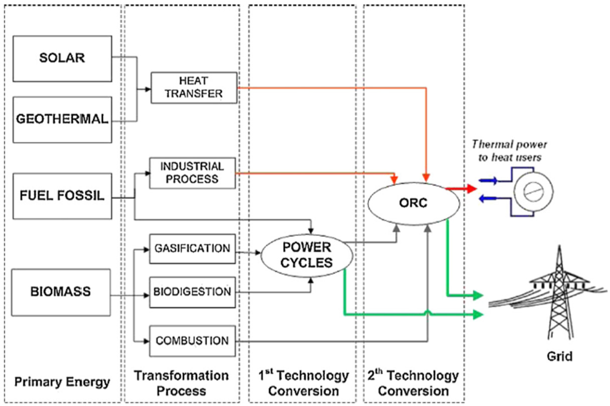
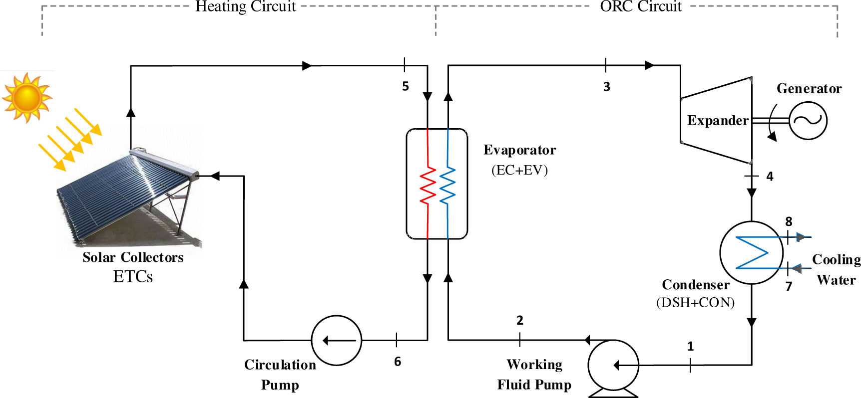
Figure 2 illustrates the schematic diagram of the proposed ORC driven by a solar thermal energy source. The solar ORC system consists mainly of two circuits: solar heating circuit and organic fluid circuit. The ORC circuit consists of evaporator, expander, condenser and working fluid pump. The evaporator is divided into two sections, namely Economizer (EC) and Evaporator (EV). The condenser has two sections, namely De-Superheater (DSH) and Condenser (CON). Water is used as a Heat Transfer Fluid (HTF) and it is heated up to the desired temperature in the solar heating circuit using an array of ETCs.
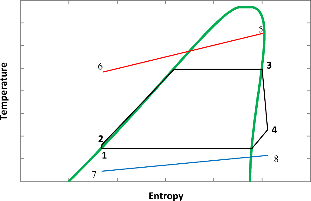
The liquid organic fluid (state 1) is first pumped to a high pressure (state 2) in the working fluid pump. The high pressure fluid then passes through the evaporator where it absorbs heat from the hot water. During this process, the temperature of the working fluid firstly increases to its saturation temperature in the EC section. Then the fluid is fully converted into vapor as it passes through the EV section (state 3). The vapour with high temperature and pressure then flows across the expander to produce mechanical work, which can be converted into electricity via a generator. The expanded working fluid (state 4) then passes through a condenser where it is cooled down to a saturated vapor in the DSH section and then fully condensed in the CON section (state 1). The liquid working fluid is then pumped again to repeat the cycle. The corresponding T-s diagram of the full cycle is shown in Figure 3.
Schematic diagram of the solar ORC system
T-s diagram of the solar ORC system
In order to derive the thermodynamic mathematical model for the whole system, each component in the system is considered as a control volume. The principles of mass and energy conservation are then applied to each control volume. The following general assumptions are considered in the analysis of the overall system and its subsystems:
In all components, processes are assumed to be continuous and under steady state conditions;
The changes in kinetic and potential energy are not considered;
The expander and pump are adiabatic with fixed isentropic efficiencies;
The heat losses and pressure drop in all system components and piping are neglected.
The mass balance equation can be expressed as:
(1)
The general energy balance equation, based on the first law of thermodynamics, can be written as follows:
(2)
where and represent the rates of heat transfer into the control volume and work done by the control volume, respectively, and and h represent the mass flow rate and specific enthalpy of the streams crossing the control volume boundaries, respectively.
The heat received by the solar collector and transferred to the HTF can be calculated based on the collector energy balance equation as a function of the collector efficiency:
(3)
where Gt is the total solar irradiance on the solar collector surface, Acol is the collector aperture area, ηcol is the solar collector efficiency and is the hot water mass flow rate in the solar heating circuit.
The thermal efficiency of the solar collector can be expressed in terms of the solar irradiance, mean collector temperature and ambient temperature as:
(4)
Here, a0, a1 and a2 are efficiency equation constants for the solar collector. The ETC used in this study is VR12 from ESTEC GmbH. Table 1 presents the efficiency equation constants for VR12 [22], [23].
ETC efficiency equation constants
| Constant | a0 [-] | a1 [W/m2K] | a2 [W/m2 K2] |
|---|---|---|---|
| Value | 0.825 | 0.91 | 0.6 × 10⁻³ |
The electric power consumed by the working fluid pump is calculated as:
(5)
where is the working fluid mass flow rate, ηp is the pump efficiency and ηM is the electric motor efficiency.
The total heat transfer rate in the evaporator (), from the HTF into the working fluid is given by:
(6)
where Te,i and Te,o are the temperatures at the inlet and outlet of hot water stream, respectively.
The expander electric output power is given by:
(7)
where ηt and ηg are the expander isentropic efficiency and the generator efficiency, respectively.
The condenser heat rejection rate (), can be expressed as:
(8)
where is the cooling water mass flow rate, and Tc,i and Tc,o are the cooling water temperatures at the inlet and outlet of the condenser, respectively.
The net output power generated by the solar ORC system is defined as:
(9)
The thermal efficiency of the ORC is the ratio of the net power output to the heat input in the evaporator. It can be expressed as:
(10)
The overall efficiency of the solar ORC system can be defined as follows:
(11)
The Back Work Ratio (BWR) is the ratio between the pump power and the expander power:
(12)
In addition to the system efficiency, which is used to evaluate the system from a thermodynamic point of view, other parameters are needed to be defined to provide more insight into the technical feasibility and economic competitiveness of the solar ORC. The maximum operating pressure, required solar collector area, the total heat transfer surface area of the heat exchangers and the Volume Flow Ratio (VFR) between the outlet and inlet of the expander are among the key parameters used in this study.
The sum of product of overall heat transfer coefficient and heat transfer area (UAtot), which is used to evaluate the total heat exchanger cost, can approximately indicate the requited total area of heat exchangers [24]. The UAtot can be determined in terms of evaporator and condenser heat transfer capacities as follows:
(13)
The product of overall heat transfer coefficient and heat transfer area of the evaporator and condenser can be obtained as the sum of their heat exchanger’s sections:
(14)
(15)
The product UAi for each section i of the heat exchanger is calculated using the Logarithmic Mean Temperature Difference (LMTD) approach as in Incropera et al. [25]:
(16)
where is the heat transfer rate in section i. The logarithmic mean temperature difference (LMTDi), is defined as follows:
(17)
where ∆Tmax,i and ∆Tmin,i are the maximal and minimal temperature differences at i section terminals of the heat exchangers, respectively.
The VFR is defined as the ratio between the volume flow rates at the outlet and inlet of the expander:
(18)
The summer conditions of Newcastle upon Tyne (54° 59' N, 1° 37' W) were selected to evaluate the solar ORC system performance. Measurements of the global irradiance at Newcastle upon Tyne have been carried out during summers of 1994 and 1995. It has been reported that the maximum observed global irradiance values are between 636 W/m2 and 978 W/m2 [26]. In this work, the global solar irradiance value was set to 700 W/m2. The system was examined using R600 and R245fa as working fluids, for their common use in low-temperature applications [27], [28]. The main thermodynamic, safety and environmental parameters of the selected fluids are listed in Table 2.
| Property | R245fa | R600 |
|---|---|---|
| Thermodynamic properties | ||
| M [kg/kmol] | 134.05 | 58.12 |
| Tbp [°C] | 14.9 | –0.55 |
| Tc [°C] | 154.05 | 151.98 |
| Pc [bar] | 36.4 | 37.9 |
| Safety properties | ||
| ASHRAE 34 group | B1 | A3 |
| Environmental properties | ||
| ODP | 0 | 0 |
| GWP [100 yr] | 1,030 | – 20 |
| Fluid type | Dry | Dry |
The solar ORC system is designed to produce 10 kW net power output using a set of operating parameters listed in Table 3. Saturated vapor was assumed at the expander inlet and the vapor quality at the expander outlet was set to a minimum value of 0.95.
Operating parameters of the solar ORC
| Parameter | Value |
|---|---|
| Net output power [kWe] | 10 |
| Heat source inlet temperature [°C] | 120 |
| Cooling water inlet temperature [°C] | 18 |
| Condensation temperature [°C] | 35 |
| Evaporator pinch point temperature [°C] | 8 |
| Condenser pinch point temperature [°C] | 5 |
| Ambient temperature [°C] | 25 |
| Maximum ORC operating temperature [°C] | 100 |
| Expander isentropic efficiency [%] | 75 |
| Pump isentropic efficiency [%] | 80 |
| Electric generator efficiency [%] | 96 |
| Pump motor efficiency [%] | 96 |
A complete thermodynamic analysis was performed for the system shown in Figure 2. The simulation model of the proposed solar ORC system was developed using Thermolib 5.2 toolbox [31], developed by EUtech Scientific Engineering GmbH, in a MATLAB/Simulink environment. The working fluid properties were evaluated using the built-in thermo-physical properties database of Thermolib. To validate the developed Thermolib simulation model, comparisons between the present model results and those obtained from Fu et al. [32] were performed by setting the same operating conditions and using the same working fluid, i.e., R245fa. The mass flow rate of R245fa was kept at a fixed value of 11.85 kg/s. The validation was conducted at constant heat source and condensation temperatures of 133.9 °C and 39 °C, respectively. The comparisons were carried out for a range of the heat source mass flow rates of 10.0-25.0 kg/s. The present model results and those obtained from [32] for the variations of the system efficiency with the heat source mass flow rate are shown in Table 4. It can be seen that the predicted results from the present model and those published in [32] are in very good agreement. The maximum relative deviation between the two results is 2.29%.
Comparison of the simulation model results with data from [32]
| Heat source mass flow rate [kg/s] | System efficiency [%] |
System efficiency [%] |
Deviation [%] |
|---|---|---|---|
| 10 | 7.59 | 7.42 | 2.29 |
| 15 | 9.48 | 9.36 | 1.28 |
| 20 | 10.20 | 10.12 | 0.79 |
| 25 | 10.58 | 10.50 | 0.76 |
The comparative assessment of the selected working fluids was carried out when the same net output power of 10 kW is produced using the set of operating parameters and specifications listed in Table 3.
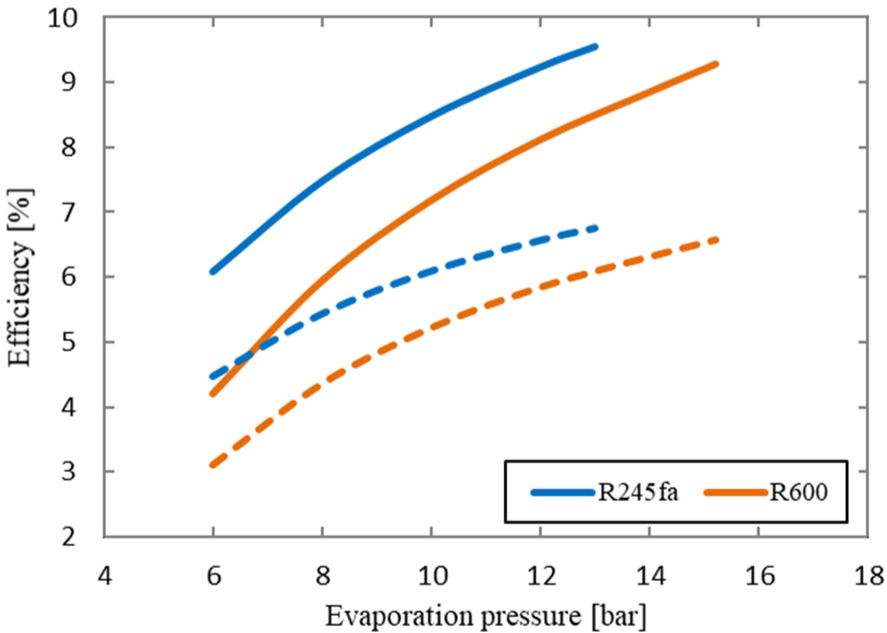
Figure 4 shows the variation of the ORC efficiency and overall system efficiency with the evaporation pressure for both working fluids. It can be seen that for the two working fluids, both the ORC efficiency and overall plant efficiency significantly increase as the evaporation pressure increases. In addition, R245fa achieves higher efficiencies than R600 over the whole range of the evaporation pressure. At the highest evaporation pressure, the ORC efficiency and overall system efficiency for R245fa are 9.54% and 6.75%, respectively. Although the overall system efficiency are relatively low, it is considered reasonable for such an ORC system driven by a solar heat source having a limited temperature of only 120 °C which in turn cannot be achieved using the traditional Rankine cycles.
Variation of ORC efficiency (solid line) and overall system efficiency (dash line) with evaporation pressure
The variation of the working fluid mass flow rate with the evaporation pressure for both working fluids is shown in Figure 5. The figure shows a decrease in the working fluid mass flow rate as the evaporation pressure increases. This is due to the fact that at the same output power, the increase in the evaporation pressure yields enthalpy difference increase across the expander and hence a decrease in the mass flow rate. It can be seen that the ORC system using R245fa as a working fluid requires higher mass flow rate than that with R600.
Variation of working fluid mass flow rate with evaporation pressure
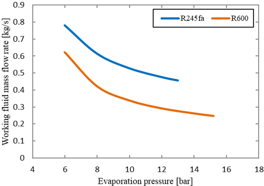
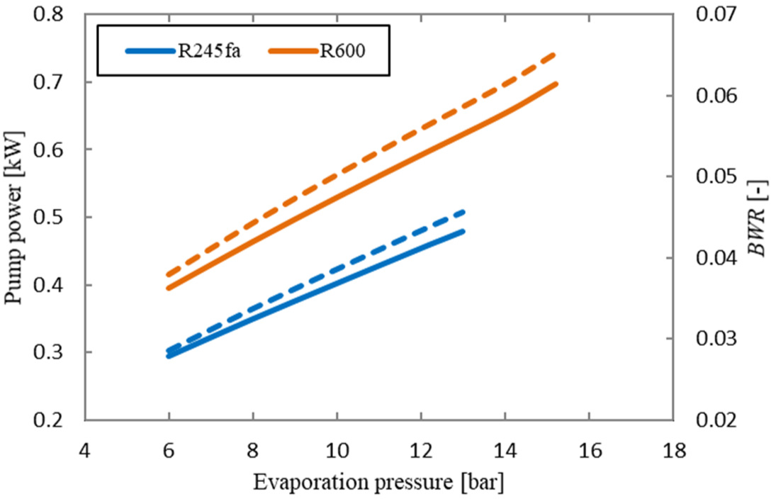
Figure 6 shows the power consumed by the pump and the BWR, vs. the evaporation pressure. The figure logically illustrates that the pump power increases with increasing the evaporation pressure. As it can be seen, the use of R600 leads to comparatively high pumping power and, consequently, high BWR values over the whole range of the evaporation pressure. Also, it is indicated from the figure that the values of pump power for R600 and R245fa forms about 6.5% and 4.5% of the expander power, respectively.
Variation of pump power (solid line) and BWR (dash line) with evaporation pressure
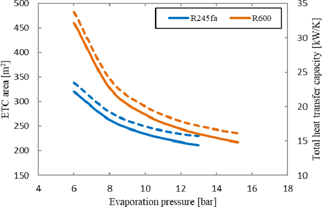
The solar collector area and the size of the heat exchangers play a vital role in the economics of the solar ORC system. Figure 7 shows results on determination of the total solar collector area and the total product of overall heat transfer coefficient and heat transfer area (UAtot) of the heat exchangers, required for producing the 10 kW net power output. It is obvious that both the solar collector area and UAtot decrease sharply with the increase of the evaporation pressure for both fluids. The system requires a smaller collector area when R245fa is used and this value is 212 m2 at evaporation pressure of 13 bar. The system will require a collector area of about 235 m2 when R600 is used at the same evaporation pressure. Smaller UAtot values indicate smaller heat exchangers area that is required for satisfying the heat exchange process, leading to lower equipment cost. R245fa has lower UAtot values which ensure a smaller heat exchanger area compared to those for R600.
Variation of ETC area (solid line) and UAtot (dash line) with evaporation pressure
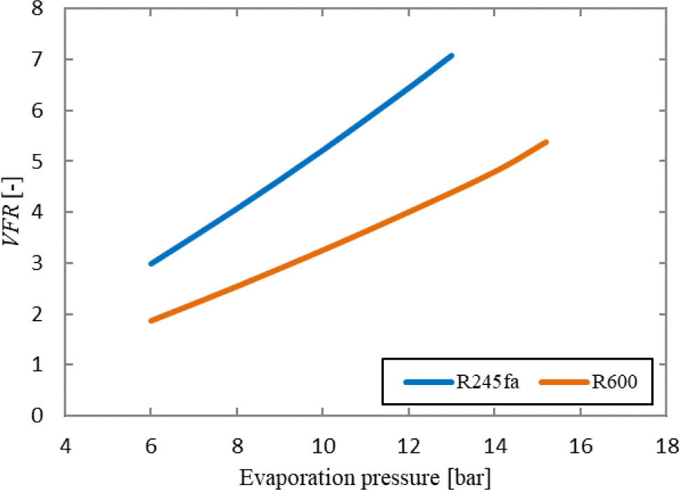
The variation of the VFR, with the evaporation pressure for the investigated working fluids is illustrated in Figure 8. Increased VFR values are associated with large expander size [33]. Moreover, lower VFR values ensure the higher isentropic expander efficiency. VFR should be less than 50 in order to achieve the isentropic efficiency higher than 80% [34]. As it can be observed in Figure 8, VFR always increases as the evaporation pressure increases. R600 shows smaller VFR values over the entire range of the evaporation pressure which in turn leads to the smaller expander size and higher efficiency.
Variation of VFR with evaporation pressure
In this paper, a thermodynamic feasibility analysis of a low-temperature solar-driven ORC system was performed. Evacuated tube solar collectors were used as a heat source providing hot water with a temperature of 120 °C. The performance of the solar ORC system was investigated using two different working fluids over a wide range of the evaporation temperature. Different parameters, which directly indicate the system components’ sizing, were used in order to evaluate the thermal and economic performance of the system.
Although the heat source used was relatively low, 120 °C, the results showed that the solar ORC system is able to achieve an overall system efficiency of 6.75%. In terms of the thermodynamic performance, R245fa provides higher ORC and overall system efficiencies. In terms of the economic performance, R245fa is more cost-effective than R600 as the former ensures smaller areas of both the solar collector and the heat exchangers. However, R600 provides a lower VFR, resulting in a smaller size of the expander with higher efficiency. Considering the safety and environmental issues, the use of R600 requires extra engineering precautions due to its high inflammability.
The authors gratefully acknowledge the financial support provided by the Cultural Affairs Department of the Libyan Embassy in London.
| A | area | [m2] |
| BWR | back work ratio | [-] |
| Cp | specific heat | [J/kgK] |
| Gt | total solar irradiance | [W/m2] |
| h | specific enthalpy | [J/kg] |
| LMTD | logarithmic mean temperature difference | [K] |
| mass flow rate | [kg/s] | |
| P | pressure | [bar] |
| heat transfer rate | [W] | |
| T | temperature | [oC] |
| UA | heat transfer capacity | [W/K] |
| volume flow rates | [m3/s] | |
| v | specific volume | [m3/kg] |
| VFR | volume flow ratio | [-] |
| power | [W] |
| η | efficiency | [-] |
| ETC | Evacuated Tube Solar Collector |
| GWP | Global Warming Potential (relative to CO2) |
| ODP | Ozone Depletion Potential (relative to R11) |
| ORC | Organic Rankine Cycle |
- A Review of Working Fluid and Expander Selections for Organic Rankine Cycle, 2013,
- Development and Analysis of a Solar and Wind Energy Based Multigeneration System, 2015,
- Preliminary Design and Controlling Strategies of a Small-Scale Wood Waste Rankine Cycle (RC) with a Reciprocating Steam Engine (SE), 2009,
- A Review of Thermodynamic Cycles and Working Fluids for the Conversion of Low-Grade Heat, 2010,
- Energetic and Economic Investigation of Organic Rankine Cycle Applications, 2009,
- Performance and Design Optimization of a Low-Cost Solar Organic Rankine Cycle for Remote Power Generation, 2011,
- A Technical, Economical and Market Review of Organic Rankine Cycles for the Conversion of Low-Grade Heat for Power Generation, 2012,
- and García-Rodríguez, L., Analysis and Optimization of the Low-Temperature Solar Organic Rankine Cycle (ORC), 2010,
- Dynamic Modelling and Validation of a Commercial Scale Geothermal Organic Rankine Cycle Power Plant, 2016,
- Fluid Selection for the Organic Rankine Cycle (ORC) in Biomass Power and Heat Plants, 2007,
- Unconventional Working Fluids in Organic Rankine-Cycles for Waste Energy Recovery Systems, 2001,
- Utilization of Waste Heat from GT-MHR for Power Generation in Organic Rankine Cycles, 2010,
- Performance Analysis of a Novel System Combining a Dual Loop Organic Rankine Cycle (ORC) with a Gasoline Engine, 2012,
- Thermodynamic Performance Analysis of a R245fa Organic Rankine Cycle (ORC) with Different Kinds of Heat Sources at Evaporator, 2019,
- Solar Thermal Power Plants, 2009,
- Design and Analysis of a Novel Low-Temperature Solar Thermal Electric System with Two-Stage Collectors and Heat Storage Units, 2011,
- Fluid Selection for a Low-Temperature Solar Organic Rankine Cycle, 2009,
- Exergy Analysis of Micro-Organic Rankine Power Cycles for a Small Scale Solar Driven Reverse Osmosis Desalination System, 2010,
- Performance Evaluation of a Low-Temperature Solar Rankine Cycle System Utilizing R245fa, 2010,
- , Dynamic Modelling of a Small-Scale Standalone Solar Organic Rankine Cycle System, Proceedings of the 4th International Conference on Nuclear and Renewable Energy Resources (NuRER2014), 2014
- , Performance Evaluation for a 10 KW Solar Organic Rankine Cycle Power System to Operate in the UK Climate Conditions, Proceedings of the 3rd European Conference on Sustainability, Energy & the Environment (ECSEE2015), 2015
- Thermodynamic Analysis of Two Micro CHP Systems Operating with Geothermal and Solar Energy, 2012,
- , Thermodynamic Performance Investigation of a Small-Scale Hybrid Solar-Biomass Power System Based on Organic Rankine Cycle, Proceedings of the International Research Conference on Sustainable Energy, Engineering, Materials and Environment, 2017
- Low Grade Waste Heat Recovery with Subcritical and Supercritical Organic Rankine Cycle Based on Natural Refrigerants and Their Binary Mixtures, 2015,
- , , 2013
- Statistical Investigation of the Optimal Averaging Time for Solar Irradiance on Horizontal and Vertical Surfaces in the UK, 2000,
- Techno-economic Survey of Organic Rankine Cycle (ORC) Systems, 2013,
- , Comparative Assessment of Working Fluids for a Low-temperature Solar Organic Rankine Cycle Power System, Proceedings of the Conference on Advances in Mechanical Engineering Istanbul (ICAME2016), 2016
- Study on Thermal Efficiency of Low- to Medium-Temperature Organic Rankine Cycles Using HFO-1234yf, 2012,
- Performance Comparison and Parametric Optimization of Subcritical Organic Rankine Cycle (ORC) and Transcritical Power Cycle System for Low-Temperature Geothermal Power Generation, 2011,
- , http://www.eutech-scientific.de/products-services/thermolib.html
- Performance of a 250 kW Organic Rankine Cycle System for Off-Design Heat Source Conditions, 2014,
- Performance Analysis and Working Fluids Selection of Solar Powered Organic Rankine-Vapor Compression Ice Maker, 2013,
- Efficiency Prediction for Axial-Flow Turbines Operating with Nonconventional Fluids, 1981,


