One key component of the energy demand in the built environment is the thermal energy required for Domestic Hot Water (DHW) preparation [1]. This energy amount depends on the number of users, the temperature of the cold water and the specific DHW consumption that is related to the building/activity type [2]. Thus, this energy demand is rather constant over the year, in contrast to the thermal energy demand for space heating/cooling which is seasonally dependent [3]. Currently, mostly fossil fuels are used to meet the thermal energy demand in the built environment [4], lately, solar thermal systems were increasingly implemented in buildings mainly for DHW [5] along with other renewable energy systems [6] but also for space heating [7], enhancing the building’s sustainability and supporting the target of nearly Zero Energy Building status [8]. This concept is further extended to regional level using process network synthesis approach to implement the optimal renewable energy systems [9].
Due to the site dependent variability of the weather conditions, the efficiency of the solar thermal collector varies too and therefore their thermal energy production. Thus, the evacuated tube solar thermal collectors are recommended, as their thermal losses are lower than in the case of flat plate solar thermal collectors.
Several studies comparatively assess the dynamic behaviour, the efficiency and the economic feasibility of flat plate versus evacuated tube solar thermal collectors through numerical simulations and experimental validation. Sokhansefat et al. [10] performed a thermoeconomic analysis of a flat plate and an evacuated tube solar thermal collectors in cold climatic conditions of Iran obtaining 30% more useful energy gain in the case of last ones. A similar result (33%) was experimentally obtained by Maraj et al. [11] for warm Mediterranean climatic conditions. Further improvement (up to 106%) of the thermophysical properties of working fluids were obtained by using nanofluids instead of water both in the case of flat plate and evacuated tube solar thermal collectors as reviewed by Muhammad et al. [12]. Zambolin and Del Col [13] obtained 15% more thermal energy output in the case of evacuated tube versus flat plate solar thermal collectors in Padova over a period of 19 days. Bouzenada et al. [14], based on TRNSYS simulations, showed that evacuated tube solar thermal collectors perform better than flat plate solar thermal collectors with 15% in Kingston, Canada and 31.6% in Calcutta, India.
The better performance reported for evacuated tube solar thermal collector is reflected in their higher price, the economic feasibility of flat plate vs. evacuated tube solar thermal collectors evaluated in Najera-Trejo et al. [15] indicating a return on investment of 11 years for evacuated tube and 9 years for flat plate solar thermal collector. One way to compensate the lower performance of the flat plate solar thermal collectors was proposed by Moss et al. [16] through a prototype of an evacuated flat plate solar collector for which an efficiency higher than an evacuated tube by a factor of 1.32 was reported. Soriga and Badescu [17] developed a mathematical model to describe the dynamic behaviour of a flat plate solar collector based on which numerical simulations were performed to assess their thermal capacitance, the results showing a steady-state value of 5.37 kJ K-1m-2. Even in the case of evacuated tube solar thermal collectors improvements can be obtained as in the case of a novel evacuated tube solar collector having a parallel flow manifold header with a metal foam heat exchanger [18] presenting a performance enhancement factor ranging from 1.14 to 3.20.
Another drawback of the evacuated tube solar thermal collector is the higher occupied surface because of their gross area, significantly larger than absorber area [19]. Thus, an increased available surface is needed as in the case of solar energy systems for space heating for which novel solar-thermal collectors/array with increased architectural acceptance for building integration are proposed in Visa et al. [20]. Thus, an increased coverage factor of the available surfaces can be obtained with facade integrated trapezoidal flat plate solar thermal collector as proposed in Trianti-Stourna et al. [21] where their experimentally evaluated efficiencies presented similar evolution with usual, rectangular solar thermal collectors.
Little evidence is given in the field of solar thermal systems providing DHW for sports hall in education facilities. Energy efficiency improvement is reported through solar collector implemented on Sports Centers in Athens for sports halls [22] and swimming pools [23], and a new design is proposed to retrofit an existing solar system in a sport center in Mallorca by replacing 25% of the solar thermal collectors with new and more efficient ones expecting 14% energy savings and 30% cost savings [24]. A particular aspect of these buildings consists of the specific schedule of DHW consumption: during a twenty-minute time interval every two hours, only on weekdays between 8:00 and 20:00. This aspect requires an increased storage capacity for the DHW in order to take advantage of the eventually available solar energy during the weekend.
A case study is presented in this paper, for a solar thermal system with six Flat Plate (FP) ‒ and three Evacuated Tube (ET) solar thermal collectors installed on the rooftop of the Renewable Energy Systems and Recycling Research Centre (RESREC), in the Colina Campus of the Transilvania University of Brasov, Romania. The data monitored during the entire year of 2017 are analysed and the results are comparatively discussed in the paper for the FP vs. ET solar thermal collectors.
The FP and ET solar thermal collectors are compared in terms of specific thermal energy output and efficiency experimentally obtained during 2017. Thermal energy output is evaluated based on measured parameters (volumetric flow rate in each circuit, temperature at each solar thermal collector inlet and outlet). Further, the received global solar energy is evaluated based on the on-site measured horizontal global and diffuse solar irradiance. All the measured parameters are stored in a data logger with a frequency of one per minute. The efficiency is further evaluated as the ratio between the thermal energy output and the received global solar energy.
The specific thermal energy for each solar thermal collector (Et) is calculated using:
(1)
where Pt is the thermal power of solar thermal collector calculated with:
(2)
where ṁ [kg/s] is the measured mass flow rate of the fluid through the solar thermal collector, c [J/kg°C] is the specific heat at constant pressure of the antifreeze thermal fluid, ti,o [°C] are the measured solar thermal collector inlet/outlet temperature, Sa [m²] is the absorber area of the solar thermal collector.
The efficiency for each solar thermal collector is further calculated with:
(3)
where Es is the solar energy received by the solar thermal collector, calculated with:
(4)
where Gn is the global solar irradiance received by the solar thermal collector, calculated with:
(5)
where Bn is the direct solar irradiance received by the solar thermal collector, calculated with:
(6)
The available direct solar irradiance (B) is calculated based on infield measured global (Gh) and diffuse (Dh) horizontal solar irradiance and calculated solar altitude angle (α):
(7)
The solar altitude angle (α) varies with the earth declination ((), site latitude (() and hour angle (ω), all of them being calculated with well-known equations as in [24], [25].
The incidence angle (ν) is calculated based on the pairs of altitude and azimuth angles defining the solar ray direction (α and () and the normal of the solar thermal collector (αn and (n) using:
(8)
Dn is the received diffuse solar irradiance, calculated using:
(9)
where Dh is the measured horizontal diffuse solar irradiance and αn is the altitude angle of the solar thermal collector.
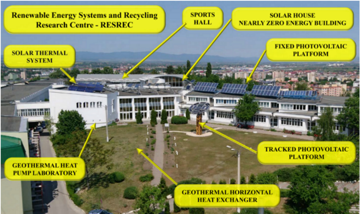
A complex research infrastructure was developed in the Colina Campus of the Transilvania University of Brasov, Romania, in the RESREC. As presented in Figure 1, this infrastructure consists of a Solar House designed to be a Nearly Zero Energy Building [8] having implemented passive solar design principles and an renewable based energy mix consisting of a ground coupled heat pump system for heating and cooling, one fixed and one tracked photovoltaic platform, both grid connected, to yearly balance the electrical energy demand of the heat pump system along with the lighting and appliances of the Solar House, and a solar thermal system providing DHW for the Solar House and (mainly) for the locker rooms of a nearby Sports Hall. Based on these facilities, the energy demand (thermal and electrical) of the Solar House is covered up to 84% using renewable energy sources and 52% in the case of the energy demand for DHW preparation for the Sports Hall is also prepared using renewable energy sources.
Renewable energy systems installed in the RESREC Research Centre in the Colina Campus of the Transilvania University of Brasov, Romania
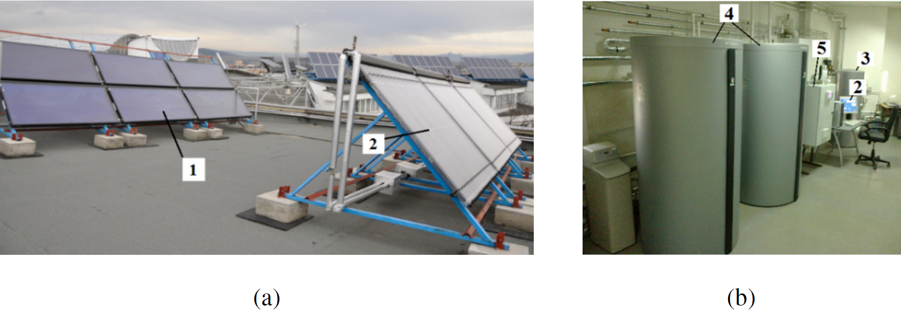
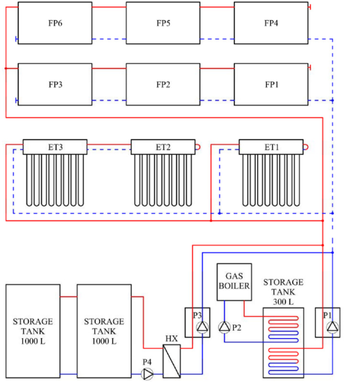
The solar thermal system (Figure 2 and Figure 3) consists of six FP (1) and three ET (2) solar thermal collectors installed on the rooftop at an optimal tilt angle of 42° (Figure 2a). The thermal energy is stored in a 300 L tank (3) where DHW is heated up to 60 °C and, after this temperature is reached, the exceeding thermal energy is transferred through a Heat Exchanger (HX) in two tanks of 1,000 L each (4) where the storage temperature is increased up to 100 °C. A gas condensing boiler is used as a backup source when the solar energy is scarce. The storage tanks, gas boiler, controllers and monitoring systems are installed in a ground floor laboratory (Figure 2b).
Solar thermal system installed in the in the Colina Campus of RESREC Research Centre: solar thermal collectors installed on the rooftop (a) and storage tanks, controllers and monitoring system installed in the laboratory (b)
The solar thermal collectors are serially/parallely connected (Figure 3) in order to evaluate the influence of thermal fluid flow rate on the solar thermal conversion efficiency for each solar thermal collector type, to this end, the volumetric flow rate is measured in each circuit and each solar thermal collector is equipped with temperature sensors at the inlet and outlet connections, allowing thus to evaluate the thermal energy output.
Hydraulic scheme of the solar thermal system with FP and ET solar thermal collectors
The main characteristics of the six FP (FP-STC) and of the three ET (ET-STC) solar thermal collectors are presented in Table 1.
Main characteristics of the installed solar thermal collectors
| Model | Type | Absorberarea (Sa) [m²] | Nominalefficiency (η0) | First order coefficient of the collector efficiency (k1) [W/m²K] | Second order coefficient of the collector efficiency (k2) [W/m²K²] |
|---|---|---|---|---|---|
| Vitosol 100 SH1 | FP-STC | 2.32 | 0.81 | 3.48 | 0.0164 |
| Vitosol 300 SP3 | ET-STC | 3.07 | 0.784 | 1.36 | 0.0045 |
A DeltaT weather station is installed on a nearby rooftop to measure the horizontal global (Gh) and horizontal diffuse (Dh) solar irradiance through a SPN1 pyranometer matching “World Meteorological Organization Good quality pyranometer” classification (±5% overall accuracy), along with the outdoor air temperature and relative humidity with a RHT2 sensor having a high temperature precision of ±0.1 °C and a 2% RH accuracy, wind speed with an AN4 anemometer (±0.5 m/s accuracy) and wind direction with a WD4 wind vane (±2% accuracy), and precipitation with RG2 rain gauge having a ±2% accuracy. Data are monitored continuously and stored in a DL2e data logger (at a sample rate of 1 per minute for solar irradiance and 10 minutes for the other parameters), data stored in the data logger are downloaded monthly to a database developed on a computer.
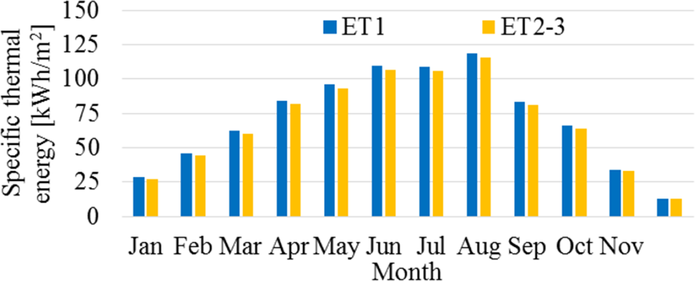
The data monitored during the entire 2017 year were processed based on the proposed methodology, the solar thermal system produced 17,412 kWh of thermal energy to prepare DHW covering thus 52% of the DHW thermal energy demand of the Solar House and locker rooms of a Sports Hall. Among the ET solar thermal collectors, the specific thermal energy output of the serially connected ones (ET2-3) is slightly lower than of the single connected one (ET1) due to the increased inlet temperature in the solar thermal collector ET2 (Figure 4).
Monthly specific thermal energy produced by the ET solar thermal collectors
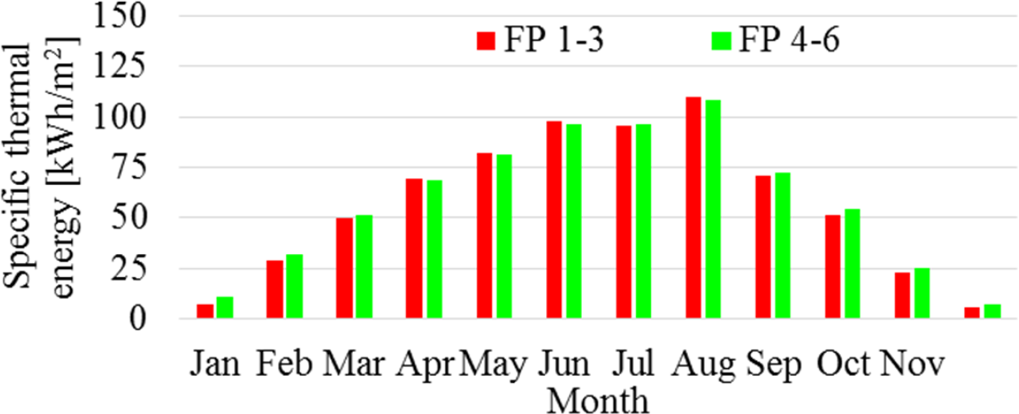
Comparing the specific thermal output of the FP solar thermal collectors, the upper row (FP 4-6) performs better than the lower row (FP 1-3) during winter months, probably due to their higher position avoiding shadowing from the ET solar thermal collectors installed in front of them (Figure 5).
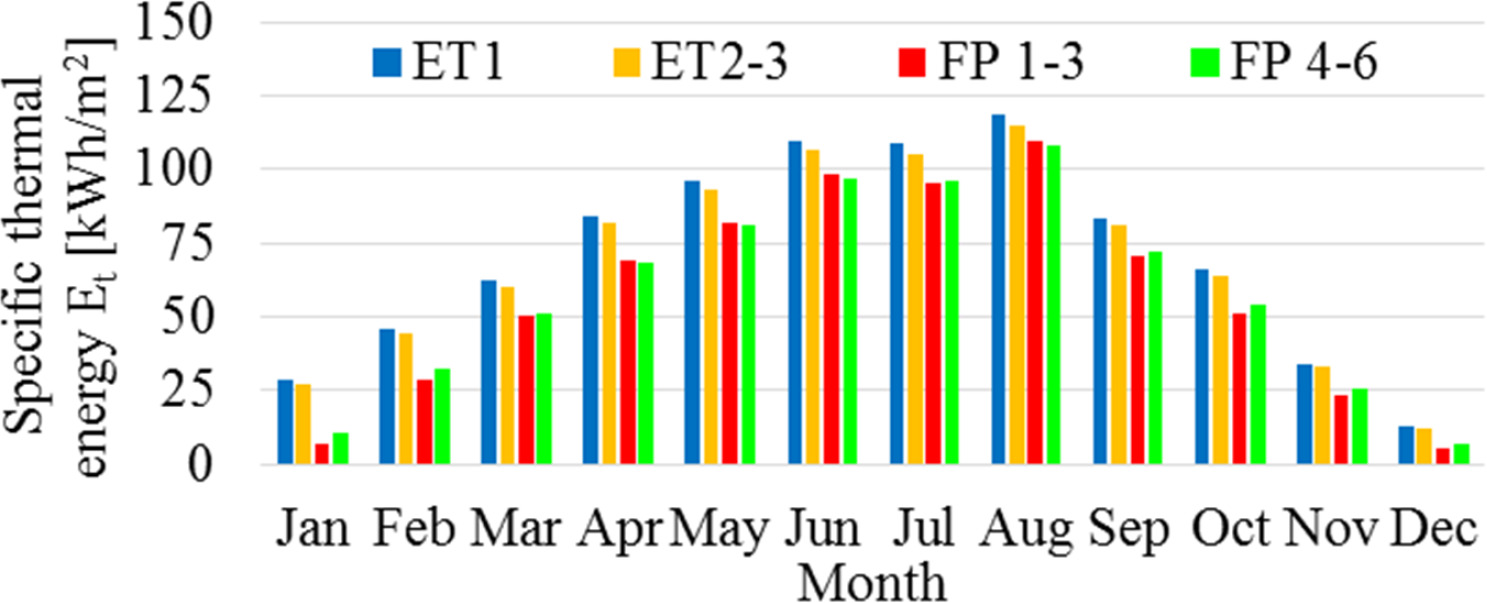
The monthly specific thermal energy values produced by each solar thermal collector are comparatively presented in Figure 6. The results shows that, during the entire year the ET performs better than FP solar thermal collectors, higher differences being registered during the cold months (January and February).
Monthly specific thermal energy produced by the FP solar thermal collectors
Monthly specific thermal energy produced by the ET and FP solar thermal collectors
The solar energy received in the solar thermal collectors plane was calculated based on the onsite measured horizontal global (Gh) and diffuse (Dh) solar irradiance and the results are plotted in Figure 7. The yearly received solar energy reaches a value of 1,375 kWh/m2.
Monthly received solar energy calculated based on onsite measured solar irradiance
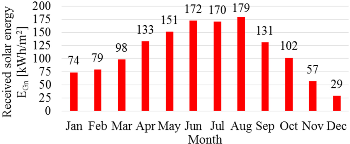
The monthly specific thermal energy produced by the Evacuated Tube (ET) and Flat Plate (FP) solar thermal collectors (Figure 6) follows the monthly variation of the received solar energy (Figure 7). For a qualitative assessment the monthly efficiency of each solar thermal collector was evaluated as the ratio of the monthly specific thermal energy output (Et) and received solar energy (EGn). The results are comparatively presented in Table 2. Lower efficiencies were obtained in the case of FP solar thermal collectors during winter months when the outdoor air temperature was also lower (onsite measured monthly mean outdoor air temperature varies between -7.78 °C in January and 20.56 °C in August).
Monthly efficiency of ET and FP solar thermal collectors
| Month | ET1 | ET 2 + 3 | FP 1 + 2 + 3 | FP 4 + 5 + 6 | Total |
|---|---|---|---|---|---|
| January | 0.389 | 0.366 | 0.099 | 0.149 | 0.224 |
| February | 0.580 | 0.560 | 0.366 | 0.406 | 0.458 |
| March | 0.633 | 0.616 | 0.513 | 0.523 | 0.559 |
| April | 0.633 | 0.615 | 0.523 | 0.518 | 0.560 |
| May | 0.636 | 0.616 | 0.544 | 0.537 | 0.574 |
| June | 0.639 | 0.619 | 0.572 | 0.563 | 0.591 |
| July | 0.640 | 0.620 | 0.561 | 0.566 | 0.589 |
| August | 0.662 | 0.644 | 0.615 | 0.605 | 0.626 |
| September | 0.639 | 0.620 | 0.542 | 0.552 | 0.579 |
| October | 0.649 | 0.630 | 0.506 | 0.536 | 0.567 |
| November | 0.597 | 0.577 | 0.406 | 0.446 | 0.489 |
| December | 0.449 | 0.425 | 0.192 | 0.242 | 0.303 |
| Total | 0.619 | 0.600 | 0.504 | 0.513 | 0.547 |
A solar thermal system of 6 FP and 3 ET solar thermal collectors is presented in the paper along with its specific thermal energy output and efficiency obtained based on experimental values. This solar thermal system is a part of a complex infrastructure developed in the RESREC in the Transilvania University of Brasov, Romania. During 2017, the solar thermal system produced 17,412 kWh of thermal energy to prepare DHW for the locker rooms of the Sports Hall, covering thus 52% of its DHW thermal energy demand.
During the entire year, ET performs better than FP solar thermal collectors, higher differences being registered during the cold months. For January, the monthly efficiency of the ET solar thermal collector was 0.389 while FP solar thermal collectors’ monthly efficiency dropped to 0.099. Thus, for sites with similar climate (continental temperate), ET solar thermal collectors could be a better option when implementing solar thermal systems.
When the ET solar thermal collectors are serially connected (ET2-3), their specific thermal output is slightly lower than of the single connected one (ET1) the efficiency decreasing by 0.019 on average. Thus, if there is no need of higher outlet temperatures, it is recommended to install the ET solar thermal collectors in parallel.
Comparing the specific thermal output of the FP solar thermal collectors, the upper row (FP 4-6) performs better than the lower row (FP 1-3) during winter months, probably due to their higher position avoiding shadowing from the ET solar thermal collectors installed in front of them.
| B | available direct solar irradiance | [W/m²] |
| Bn | direct solar irradiance received by the solar thermal collector | [W/m²] |
| c | specific heat at constant pressure of the thermal fluid | [J/kg°C] |
| Dh | infield measured diffuse horizontal solar irradiance | [W/m²] |
| Dn | diffuse solar irradiance received by the solar thermal collector | [W/m²] |
| Es | solar energy received by the solar thermal collector | [kWh/m²] |
| Et | specific thermal output of each solar thermal collectors | [kWh/m²] |
| Gh | infield measured global horizontal solar irradiance | [W/m²] |
| Gn | global solar irradiance received by the solar thermal collector | [W/m²] |
| ṁ | mass flow rate of the fluid through the solar thermal collector | [kg/s] |
| Pt | thermal power of solar thermal collector | [W] |
| Sa | solar thermal collector absorber area | [m²] |
| ti | solar thermal collector inlet temperature | [°C] |
| to | solar thermal collector outlet temperature | [°C] |
| Greek letters | ||
| α | solar altitude angle | [°] |
| αn | solar thermal collector altitude angle | [°] |
| δ | Earth declination | [°] |
| η | solar thermal collector efficiency | [-] |
| φ | latitude | [°] |
| υ | incidence angle | [°] |
| ω | hour angle | [°] |
| ψ | solar azimuthal angle | [°] |
| ψn | solar thermal collector azimuthal angle | [°] |
- , Future Trends for Solar Energy Use in Nearly Zero Energy Buildings, Advances in Solar Heating and Cooling, 2016
- , Refrigerating and Air-Conditioning Engineers, ASHRAE Handbook—Fundamentals, 2013
- ,
Solar Trigeneration: A Transitory Simulation of HVAC Systems Using Different Typologies of Hybrid Panels ,Journal of Sustainable Development of Energy, Water and Environment Systems , Vol. 2 (1),pp 1-14 , 2014, https://doi.org/https://doi.org/10.13044/j.sdewes.2014.02.0001 - ,
Evaluation of Economic, Energy-environmental and Sociological Effects of Substituting Non-renewable Energy with Renewable Energy Sources ,Journal of Sustainable Development of Energy, Water and Environment Systems , Vol. 2 (4),pp 333-343 , 2015, https://doi.org/https://doi.org/10.13044/j.sdewes.2015.03.0025 - , The Role of Mechanisms in Sustainable Energy Systems, Transilvania University of Brasov Publishing House, 2015
- ,
Improving the Renewable Energy Mix in a Building Towards the Nearly Zero Energy Status ,Energy and Buildings , Vol. 68 (Part A),pp 72-78 , 2014, https://doi.org/https://doi.org/10.1016/j.enbuild.2013.09.023 - ,
Modelling and Control of Collecting Solar Energy for Heating Houses in Norway ,Journal of Sustainable Development of Energy, Water and Environment Systems , Vol. 5 (3),pp 359-376 , 2017, https://doi.org/https://doi.org/10.13044/j.sdewes.d5.0147 - , Directive 2010/31/EU on the Energy Performance of Buildings, Official Journal of the European Union, 2010
- ,
Optimal Renewable Energy Systems for Regions ,Journal of Sustainable Development of Energy, Water and Environment Systems , Vol. 2 (1),pp 88-99 , 2014, https://doi.org/https://doi.org/10.13044/j.sdewes.2014.02.0008 - ,
Thermoeconomic and Environmental Analysis of Solar Flat Plate and Evacuated Tube Collectors in Cold Climatic Conditions ,Renewable Energy , Vol. 115 ,pp 501-508 , 2018, https://doi.org/https://doi.org/10.1016/j.renene.2017.08.057 - ,
Comparison of the Energy Performance between Flat-plate and Heat Pipe Evacuated Tube Collectors for Solar Water Heating Systems under Mediterranean Climate Conditions ,Journal of Sustainable Development of Energy, Water and Environment Systems , Vol. 7 (1),pp 87-100 , 2019, https://doi.org/https://doi.org/10.13044/j.sdewes.d6.0228 - ,
Thermal Performance Enhancement of Flat-Plate and Evacuated Tube Solar Collectors Using Nanofluid: A Review ,International Communications in Heat and Mass Transfer , Vol. 76 ,pp 6-15 , 2016, https://doi.org/https://doi.org/10.1016/j.icheatmasstransfer.2016.05.009 - ,
Experimental Analysis of Thermal Performance of Flat Plate and Evacuated Tube Solar Collectors in Stationary Standard and Daily Conditions ,Solar Energy , Vol. 84 (8),pp 1382-1396 , 2010, https://doi.org/https://doi.org/10.1016/j.solener.2010.04.020 - ,
Performance of a Liquid Desiccant Air-Conditioner Driven by Evacuated-Tube, Flat-Plate, or Hybrid Solar Thermal Arrays ,Energy and Buildings , Vol. 117 ,pp 53-62 , 2016, https://doi.org/https://doi.org/10.1016/j.enbuild.2016.02.002 - ,
Economic Feasibility of Flat Plate vs Evacuated Tube Solar Collectors in a Combisystem ,Energy Procedia , Vol. 91 ,pp 477-485 , 2016, https://doi.org/https://doi.org/10.1016/j.egypro.2016.06.181 - ,
Performance and Operational Effectiveness of Evacuated Flat Plate Solar Collectors Compared with Conventional Thermal, PVT And PV Panels ,Applied Energy , Vol. 216 ,pp 588-601 , 2018, https://doi.org/https://doi.org/10.1016/j.apenergy.2018.01.001 - ,
Thermal Inertia of Flat-Plate Solar Collectors in Different Radiative Regimes ,Energy Conversion and Management , Vol. 111 ,pp 27-37 , 2016, https://doi.org/https://doi.org/10.1016/j.enconman.2015.12.023 - ,
Thermal Power Measurement of the Novel Evacuated Tube Solar Collector and Conventional Solar Collector During Simultaneous Operation ,Measurement , Vol. 88 ,pp 153-164 , 2016, https://doi.org/https://doi.org/10.1016/j.measurement.2016.03.054 - ,
Novel Solar-Thermal Collectors/Array with Increased Architectural Acceptance for Building Integration ,in: Building Integration of Solar Thermal Systems Design and Applications Handbook ,pp 373-391 , 2017 - ,
Outdoor Performance of a Trapeze Solar Thermal Collector for Facades Integration ,Renewable Energy , Vol. 137 ,pp 37-44 , 2019, https://doi.org/https://doi.org/10.1016/j.renene.2018.01.101 - ,
Energy Conservation Strategies for Sports Centers ‒ Part A: Sports Halls ,Energy & Buildings , Vol. 27 (2),pp 109-122 , 1998, https://doi.org/https://doi.org/10.1016/S0378-7788(97)00040-6 - ,
Energy Conservation Strategies for Sports Centers ‒ Part B: Swimming Pools ,Energy & Buildings , Vol. 27 (2),pp 123-135 , 1998, https://doi.org/https://doi.org/10.1016/S0378-7788(97)00041-8 - ,
Retrofit of a Solar System in Sport Center in Mallorca ,Energy Procedia , Vol. 91 ,pp 190-196 , 2016, https://doi.org/https://doi.org/10.1016/j.egypro.2016.06.201 - , Solar Engineering of Thermal Processes, Wiley Interscience, 2013
- , , Solar Energy Engineering: Processes and Systems, 2014


