


Urban rail transit has brought important impact on low-carbon development to reduce energy consumption and carbon emissions, as well as solve the increasing density of urban traffic. Air conditioning system, as the main energy-consuming auxiliary system, is one of the key technologies to reduce energy consumption of urban rail vehicles, especially in cold regions. Air-Source Heat Pump (ASHP) with Vapor Injection (VI) is an effective method to enhance the heating performance in cold regions, because of three main advantages [1]:
Capacity improvement in severe climate;
Capacity variation by controlling the injected refrigerant mass flow rate;
Lower compressor discharge temperature.
It has been applied since 1979 for air conditioners [2]. Hirano et al. [3] developed a heat pump coupled with liquid refrigerant injection, which worked smoothly at ambient temperature of −20 °C. Many scholars studied the ASHP with VI from different aspects, and got favourable results in the application of building air conditioning. Ma et al. [4] proposed a new sub-cooling system employing a scroll compressor with a supplementary inlet for ambient temperatures as low as −15 °C. Bertsch et al. [5] studied two-stage ASHP for residential heating and cooling applications in northern U.S. climate. Wang et al. [6] and Roh et al. [7] analysed the effect of intermediate pressure of a heat pump system using R410A vapor-injection. Redón et al. [8] investigated the optimization of subcritical two-stage VI heat pump systems. He et al. [9] carried out experimental research on high temperature VI heat pump. Some novel systems of the ASHP with VI were presented to enhance the heating performance. Wang et al. [10] proposed an ejector enhanced VI heat pump which can improve the Coefficient of Performance (COP) from 6~10%. Cho et al. [11] investigated multistage heat pumps with a sub-cooler VI and got 7.5~13.9% improvement of heating capacity and 1.1~4.7% improvement of COP. Qiao et al. [12] studied the transient characteristics of an ASHP with VI during reverse-cycle defrosting. The simulation results indicate that the energy used to melt the frost accounts for 17.7% of the total energy supply from the refrigerant flow. Xu et al. [13] experimentally researched on an R32 vapor-injected heat pump using injection subcooling, COP of VIS system can be enhanced by 11.2-13.6%.
With the development of electric vehicles, ASHP with VI is considered as a promising way to meet the heating demand since there is no waste heat from the engine. It has become a research hotspot in this area. Qin et al. [14], [15] studied injection process and compressor performance at −20 °C. Gang et al. [16] experimentally investigated a newly designed twin rotary variable speed compressor for VI heat pump in cold regions. Choi et al. [17] and Zhang et al. [18] analysed the effect of VI on heat pump system performance for electric cars. Kwon et al. [19] provided the basic performance data for the VI heat pump for an Electric Vehicle (EV) application and estimated the system performance in cold ambient regions. The working conditions have a great effect on the branch of VI, as well as the system heating performance. Appropriate control of the expander valves in two branches is very critical to both the performance and reliability of the system. Normally, the internal heat exchanger and the evaporator outlet superheating is employed as the control parameter to regulate the expansion valve opening. However, the superheating control can only make sure the outlet temperature, while the inlet two-phase temperature and pressure have more effect on the system performance. It is significant to give a real-time adjustment to get optimal performance with the change of working conditions.
So far, the application of ASHP with VI is still in the research and development stage in electric vehicles and even rarer in electric railway vehicles for there are some typical challenges for the air conditioning system, such as excessive vibration, complex working conditions and variable load demand. Also, there are some typical characteristics of the heat pump system for railway vehicles which are different from that for cars. For example, the cooling/heating capacity of the heat pump for railway vehicles is around 5-6 times of that cars, the form and material of key components, like heat exchangers are different, and the pipe route and installation of the heat pump system is different.
In this paper, a heating performance analysis program for an ASHP with VI of internal heat exchanger cycle is set up to analyse the optimal injection ratio according to the working conditions of electric railway vehicles. The research results of optimal injection ratio can present the theoretical basis for the control development of the ASHP system.
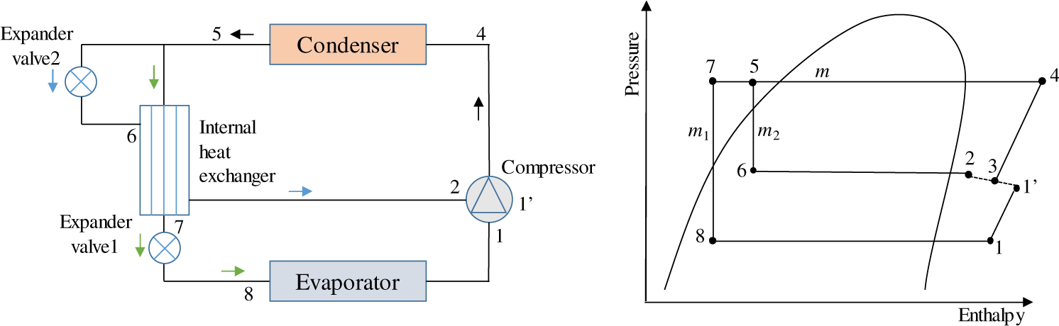
Figure 1 shows the diagram of an ASHP with VI and operation process on the pressure-enthalpy chart. The applied refrigerant is R410a. R410a is a kind of mixed refrigerant of R32 and R125. The Ozone Depletion Potential (ODP) of R410a is 0 and its Global Warming Potential (GWP) is less than 0.2. So far, it is internationally recognized as a good refrigerant substitution for air conditioning. The refrigerant discharged from the compressor (point 4) first circulates through the condenser (point 5), and then separates into two branches: one goes through the expander valve 2 (point 6), leaves the internal heat exchanger (point 2), and then goes back to the middle inlet of the compressor, another leaves the other side of the internal heat exchanger (point 7), then goes through the expander valve 1 (point 8), leaves the evaporator (point 1) and finally goes back to the suction port of the compressor. After being compressed partly (point 1’), this part of the refrigerant mixes with that from the middle inlet of the compressor (point 3) and is compressed together to be discharged. Then the cycle is completed.
Diagram of ASHP with VI
The heating capacity (), input power (P) and COP can be calculated as follows:
(1)
(2)
(3)
(4)
(5)
(6)
where is total refrigerant mass flow rate, is the mass flow rate through the evaporator, is the injection refrigerant mass flow rate, rm is the ratio of injection to total mass flow rate, h1 is refrigerant enthalpy at the suction point of compressor, h1’ is refrigerant enthalpy at the end of first compression inside of the compressor, h2 is refrigerant enthalpy at the injection hole, h3 is mixed refrigerant enthalpy inside of the compressor, h4 is refrigerant enthalpy discharged from the compressor, h5 is outlet refrigerant enthalpy of the condenser, h6 is outlet refrigerant enthalpy of the expander valve 2, h7 is main branch outlet refrigerant enthalpy of the internal heat exchanger, h8 is main branch outlet refrigerant enthalpy of the expander valve 1.
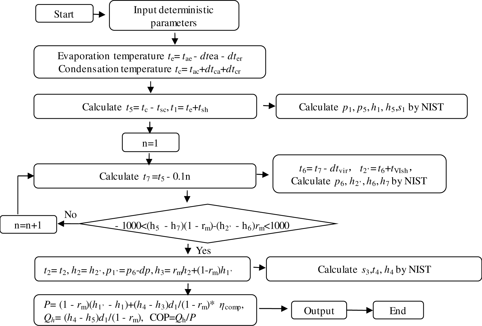
Figure 2 shows flowchart of the heating performance analysis program. In the model, the temperature difference between the fluids of heat exchangers, as well as the sub-cooling and super-heating temperature are taken as determined value. The outlet conditions of the VI branch at different injection ratio are determined by the rule that the enthalpy difference of the two sides of the economizer are equal [eq. (4)]. The right block of the input deterministic parameters gives the basic configuration in the program. These parameters can also be changed to adapt to the actual working conditions. The main highlight of the model is the determination of injection conditions. The injection pressure and temperature are calculated based on the energy balance of the internal heat exchanger through cyclic iteration. Thus, the relationship between the injection ratio and heating performance can be obtained.
Flow chart of optimization program
The inlet air temperature in the evaporator is set from −25 °C to 0 °C and that in the condenser is set from 5 °C to 20 °C, which is similar to the actual working condition of an electric railway vehicle. The injection ratio is set from 0 to 0.35. The compressor efficiency [15] and heat exchanger efficiency, as well as the other parameters are set as shown in Table 1. Here, the parameters of temperature difference in Table 1 are set according to the normal design and operation conditions [20] as a simulation example. Thus, COP of the system under different injection ratios can be calculated and the optimal injection ratio can be obtained.
Input deterministic parameters
| Parameters | Symbol | Value |
|---|---|---|
| Inlet air temperature in evaporator [°C] | tae | −25~0 |
| Inlet air temperature in condenser [°C] | tac | 5~20 |
| Injection ratio | rm | 0~0.35 |
| Temperature difference between inlet air and outlet air in evaporator [°C] | Δ(tea | 3 |
| Temperature difference between outlet air and refrigerant evaporation in evaporator [°C] | Δ(ter | 2 |
| Temperature difference between inlet air and outlet air in condenser [°C] | Δ(tca | 20 |
| Temperature difference between outlet air and refrigerant condensation in condenser [°C] | Δ(tcr | 10 |
| Temperature difference between inlet refrigerant of VI and outlet refrigerant of main branch in economizer [°C] | Δ(tvir | 1 |
| Sub-cooling temperature of outlet refrigerant of condenser [°C] | tsc | 10 |
| Super-heating temperature of outlet refrigerant of evaporator [°C] | tsh | 1 |
| Super-heating temperature of outlet refrigerant of VI [°C] | tVIsh | 0 |
| Compressor efficiency | ηcomp | 0.6[15] |
| Heat exchange efficiency | ηhe | 0.9 |
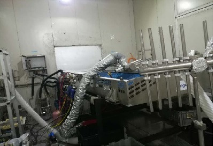
To validate the precision of the above heating performance analysis program, the experimental results of a VI ASHP with R410a developed for a rail train are applied [20]. The heating performance of the unit was measured in an enthalpy difference lab, as shown in Figure 3. The schematic diagram of the unit is similar to Figure 1. There are two Electronic Expansion Valves (EEVs) in the main branch and the VI branch, respectively. The injection ratio can be adjusted by these two EEVs. The temperature was measured by T-type thermocouples with uncertainty of ±0.5 °C. The pressure was measured by pressure transducers with uncertainty of ±0.5%. The refrigerant mass flow rate was measured by Coriolis flow meter with an uncertainty of ±0.2%.
Test bench of the VI heat pump
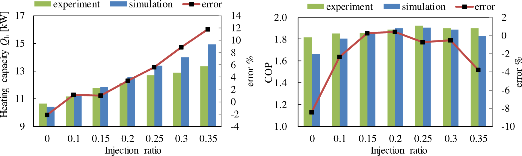
The in-cabin air temperature was set at 15 °C, and the out-cabin temperature was set at −5 °C and −20 °C. The compressor speed was set on 4,200 rpm. The out-cabin air volume flow rate was set at 4,000 m3/h, and the in-cabin air volume flow rate was set at 2,650 m3/h. Figure 4 shows the comparison between experimental results and simulated results. The heating capacity of the heat pump on no-injection condition is 10.62 kW by experiment and 9.88 kW by simulation and that on 0.35 injection ratio is 13.32 kW by experiment and 14.81 kW by simulation. Because the compressor efficiency, which is set as a constant in the program, changes with its actual working conditions, the errors deviate with the change of injection ratio. The errors of heating capacity between them are within ±12%. There is a maximum COP with the injection ratio of 0.25. The COP of the heat pump on no-injection condition is 1.82 by experiment and 1.66 by simulation and that on 0.35 injection ratio is 1.90 by experiment and 1.83 kW by simulation. The errors of COP between them are within ±9%. It is at the state of no-injection and this means the compressor efficiency set in the program deviates with the actual value. In general, the experimental and simulated results match well with each other. The experimental results show that the heating capacity of the heat pump has notable increase with the increasing of injection ratio, while the change trend of COP is different. The COP increases with the injection ratio firstly and then begins to decrease. There exists an optimal value. This optimal value is very significant for the system control strategy.
Test bench of the VI heat pump
Based on the above design program, the heating performance of the VI heat pump is analysed under different working conditions. Figure 5 shows the heating capacity changes with the injection ratio under the typical heating working condition of railway vehicles in winter. The inlet air temperature of condenser affects the condensation temperature and the enthalpy difference between the inlet and outlet of condenser gets lower with increasing condensation temperature. So, the heating capacity goes down with the increase of the inlet air temperature of condenser. With increase of injection ratio, the refrigerant mass flow rate increases and the heating capacity goes up. Here, taking the condition of 0 °C ambient temperature as an example, the heating capacity of the system with no injection decreases from 20.69 kW at 5 °C inlet air temperature of condenser to 18.92 kW at 20 °C inlet air temperature of condenser. The heating capacity of the system with 0.35 injection ratio decreases from 32.42 kW at 5 °C inlet air temperature of condenser to 28.79 kW at 20 °C inlet air temperature of condenser. On the other hand, the evaporating temperature depends on the ambient temperature and the suction density of the refrigerant decreases with decreasing evaporating temperature. As a result, the heating capacity decreases with decreasing ambient temperature (which equals to inlet air temperature of evaporator). Here, taking the conditions of −15 °C and −25 °C ambient temperature as an example, the heating capacity of the system with 0.35 injection ratio decreases from 18.54 kW to 13.02 kW at 15 °C inlet air temperature of condenser.
Heating capacity under different injection ratios
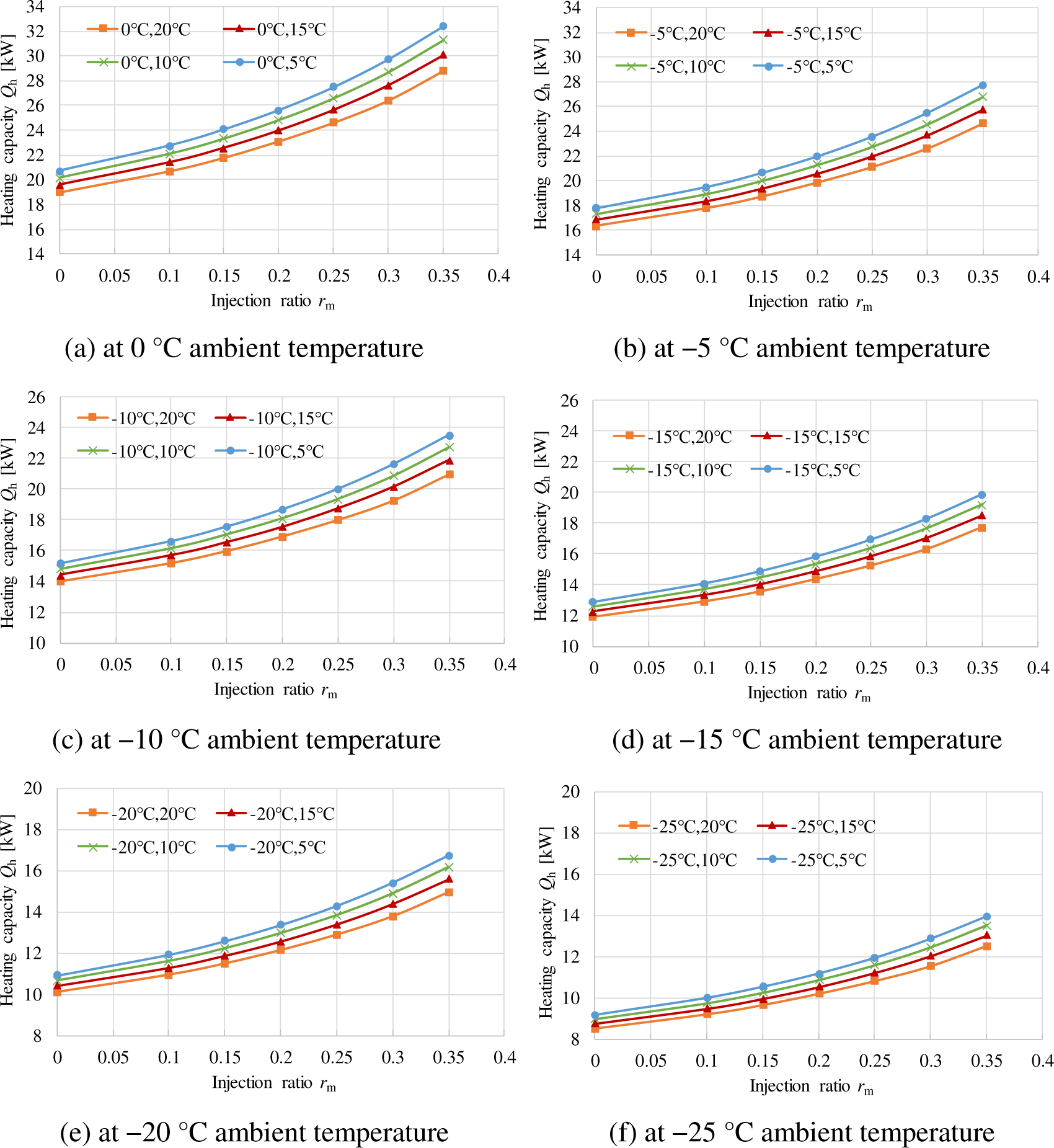
Figure 6 shows the COP under different working conditions. Figure 6a is the calculated COP change with the injection ratio at 0 °C ambient temperature. It goes up at first and then turns down with the increasing of injection ratio. This is because the input power of the compressor and heating capacity both increase with the increasing of refrigerant flow rate. There exists an optimal injection ratio at each working condition. Moreover, with the increase of the inlet air temperature of condenser from 5 °C to 20 °C, the COP gets lower for the increase of compressor pressure ratio. The optimal COP decreases from 3.76 to 2.70 and the corresponding optimal injection ratio increases from 0.12 to 0.25. Figure 6b to Figure 6f show the calculated COP at −5 °C to −25 °C ambient temperature. The decrease of ambient temperature makes the compressor pressure ratio get higher too, so the COP goes down with the decreasing of ambient temperature too. Through the above numerical analysis, it indicates that these simulated results have the same change trend with the results from the experimental results and the related researches in other publications.
COP under different injection ratios
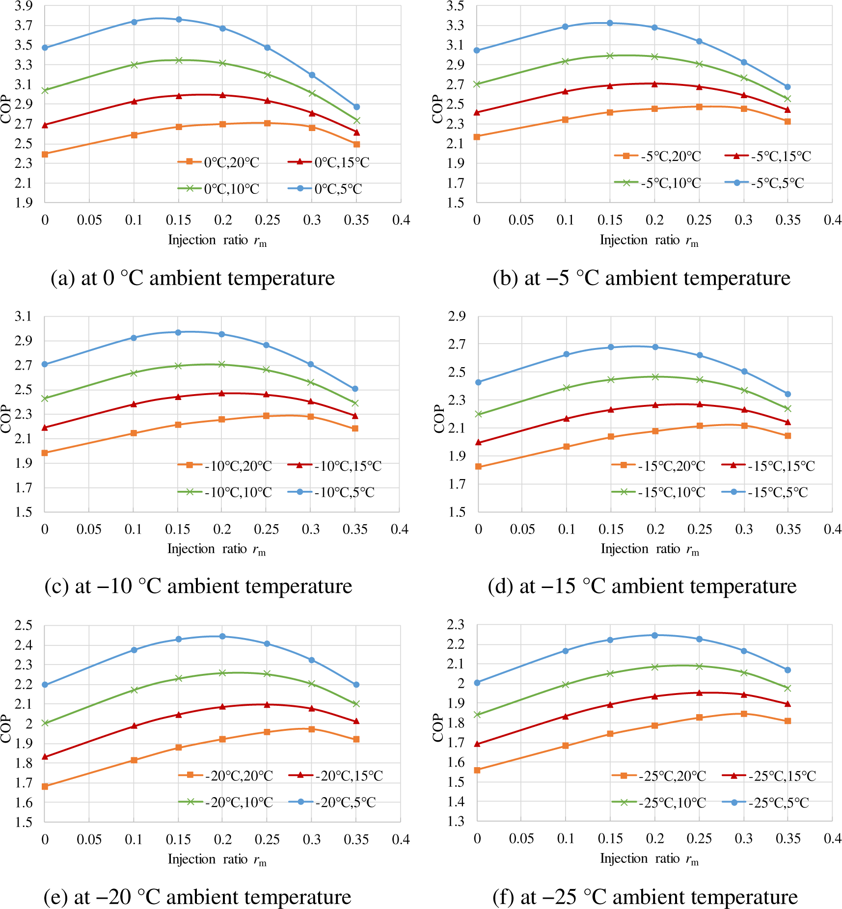
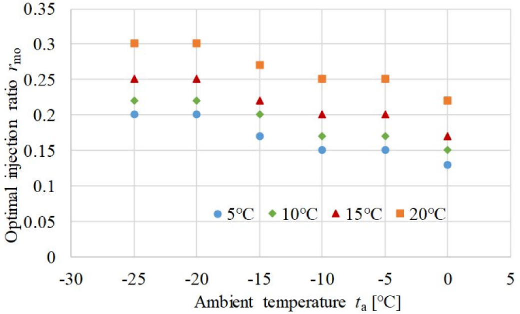
Figure 7 shows the optimal value of the injection ratio under different working conditions. The optimal value of the injection ratio gets higher with decreasing inlet air temperature of condenser. As the inlet air temperature of condenser decreases from 20 °C to 5 °C, the optimal injection ratio increases from 0.2 to 0.3 at −25 °C ambient temperature and increases from 0.13 to 0.22 at 0 °C ambient temperature. As the ambient temperature decreases from 0 °C to −25 °C, the optimal injection ratio increases from 0.12 to 0.2 at 0 °C inlet air temperature of condenser and increases from 0.22 to 0.3 at 20 °C inlet air temperature of condenser. This indicates that the optimal value is normally from 0.12 to 0.3 under the typical heating working condition of railway vehicles, with is around 50-100% fresh air ratio. According to the above analysis, the performance of the ASHT with VI is sensitive to operating conditions. It is very significant for the operation control system to have an adaptive control strategy to make the system work at optimum conditions.
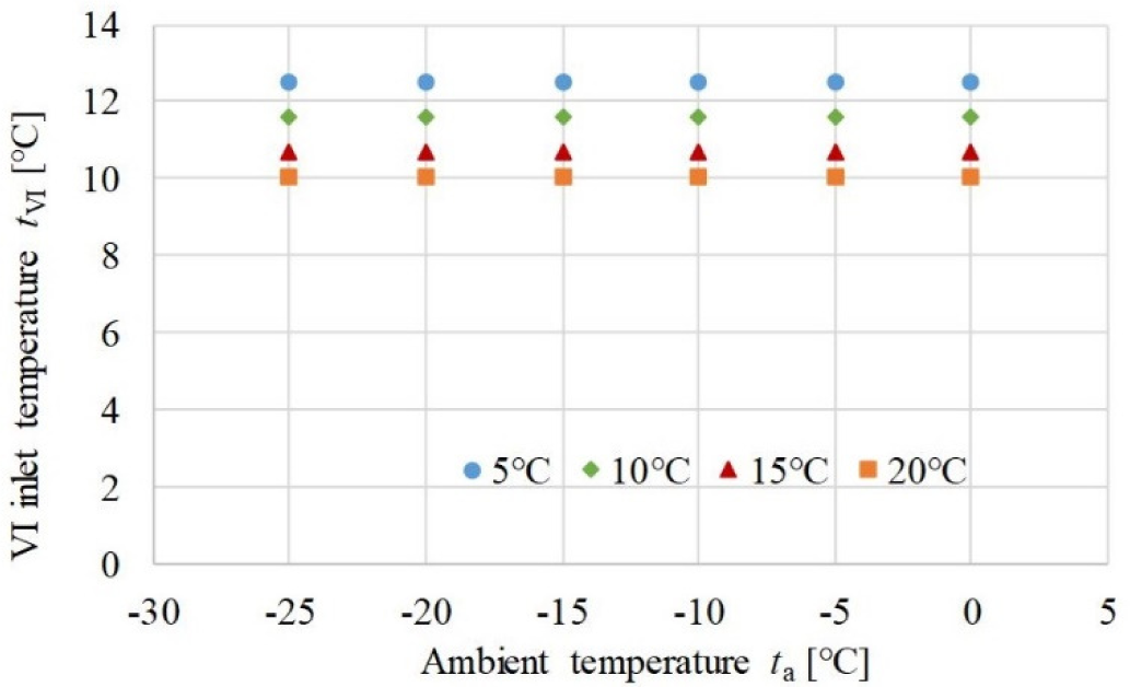
Figure 8 shows the optimal VI outlet temperature under different working conditions. The ambient temperature has little effect on the optimal VI temperature of the outlet of the internal heat exchanger. As the inlet air temperature of condenser decreases from 20 °C to 5 °C, the optimal VI temperature distributes from 10 °C to 13 °C. Based on the results, the expander valve opening of the VI branch can be controlled by its outlet temperature to get the optimal heating performance.
Optimal injection ratio
Optimal IV temperature
Through the modelling of an ASHP with VI of internal heat exchanger cycle, the optimal injection ratio based on the optimum heating COP is obtained on the typical working conditions of electric railway vehicles. The optimal value of injection ratio is mainly distributed from 0.12 to 0.3 under the typical working condition of railway vehicles in winter and accordingly the optimal VI outlet temperature of the internal heat exchanger varies from 10 °C to 13 °C. Therefore, the system design can be optimized based on the optimal value of injection ratio. Meanwhile, the system operation can be controlled by adjusting the expander valve opening of the VI branch based on its outlet temperature to get the optimal heating performance. The future work is to study the control technology of vapor injection, such as adaptive control methods, to make sure the heat pump works at optimum state under any conditions.
We would like to thank the National Key Research and Development Program of China (No. 2017YFB0103801) and the Natural Science Foundation of China (No. 51676201) for their support.
| d | density | [kg/m3] |
| h | refrigerant specific enthalpy | [kJ/kg] |
| p | refrigerant pressure | [Pa] |
| P | input power | [kW] |
| r m | mass flow rate ratio | - |
| s | refrigerant specific entropy | [kJ/kgK] |
| t | refrigerant temperature | [°C] |
| heating capacity | [kW] | |
| total refrigerant mass flow rate | [kg/s] | |
| Greek letters | ||
| η | efficiency | |
| Subscripts | ||
| 1-8 | state points shown in figure | |
| 1a | air | |
| ac | inlet air in condenser | |
| ae | inlet air in evaporator | |
| c | condensation | |
| ca | outlet air in condenser | |
| comp | compressor | |
| cr | refrigerant in condenser | |
| e | evaporation | |
| ea | outlet air in evaporator | |
| er | refrigerant in evaporator | |
| he | heat exchanger | |
| sc | sub-cooling | |
| sh | super-heating | |
| vir | vapor injection inlet refrigerant | |
| VIsh | vapor injection super-heating | |
- ,
Refrigerant Injection for Heat Pumping/Air Conditioning Systems: Literature Review and Challenges Discussions ,International Journal of Refrigeration , Vol. 34 (2),pp 402-415 , 2011, https://doi.org/https://doi.org/10.1016/j.ijrefrig.2010.09.015 - ,
Heat Pump Room Air-Conditioner Using Variable Capacity Compressor ,ASHRAE Transactions , Vol. 90 ,pp 335-349 , 1984 - ,
Study on Scroll Compressor Behaviour in Case of Liquid Refrigerant Injection ,Bioscience Biotechnology & Biochemistry , Vol. 76 (10),pp 1975-1978 , 2011, https://doi.org/https://doi.org/10.1080/00119253.1975.9934431 - ,
Experimental Investigation of Air-Source Heat Pump for Cold Regions ,International Journal of Refrigeration , Vol. 26 (1),pp 12-18 , 2003, https://doi.org/https://doi.org/10.1016/S0140-7007(02)00083-X - ,
Two-Stage Air-Source Heat Pump for Residential Heating and Cooling Applications in Northern U.S. Climates ,International Journal of Refrigeration , Vol. 31 (7),pp 1282-1292 , 2008, https://doi.org/https://doi.org/10.1016/j.ijrefrig.2008.01.006 - ,
Two-Stage Heat Pump System with Vapor-Injected Scroll Compressor Using R410A as a Refrigerant ,International Journal of Refrigeration , Vol. 32 (6),pp 1442-1451 , 2009, https://doi.org/https://doi.org/10.1016/j.ijrefrig.2009.03.004 - ,
Effects Of Intermediate Pressure on the Heating Performance of a Heat Pump System Using R410A Vapor-Injection Technique ,International Journal of Refrigeration , Vol. 34 (8),pp 1911-1921 , 2011, https://doi.org/https://doi.org/10.1016/j.ijrefrig.2011.07.011 - ,
Analysis and Optimization of Subcritical Two-Stage Vapor Injection Heat Pump Systems ,Applied Energy , Vol. 124 (7),pp 231-240 , 2014, https://doi.org/https://doi.org/10.1016/j.apenergy.2014.02.066 - ,
Experimental Study on the Performance of a Vapor Injection High Temperature Heat Pump ,International Journal of Refrigeration , Vol. 60 ,pp 1-8 , 2015, https://doi.org/https://doi.org/10.1016/j.ijrefrig.2015.08.012 - ,
Performance Analysis of a New Ejector Enhanced Vapor Injection Heat Pump Cycle ,Energy Conversion & Management , Vol. 100 ,pp 242-248 , 2015, https://doi.org/https://doi.org/10.1016/j.enconman.2015.05.017 - ,
Performance Comparison Between R410A and R32 Multi-Heat Pumps with a Sub-Cooler Vapor Injection in the Heating and Cooling Modes ,Energy , Vol. 112 ,pp 179-187 , 2016, https://doi.org/https://doi.org/10.1016/j.energy.2016.06.069 - ,
Modelling of Transient Characteristics of an Air Source Heat Pump with Vapor Injection During Reverse-Cycle Defrosting ,International Journal of Refrigeration , Vol. 88 ,pp 24-34 , 2018, https://doi.org/https://doi.org/10.1016/j.ijrefrig.2017.12.017 - ,
Experimental Research on Vapor-Injected Heat Pump Using Injection Subcooling ,Applied Thermal Engineering , Vol. 136 ,pp 674-681 , 2018, https://doi.org/https://doi.org/10.1016/j.applthermaleng.2018.03.028 - ,
Experimental Investigation on Heating Performance of Heat Pump for Electric Vehicles at −20 °C Ambient Temperature ,Energy Conversion & Management , Vol. 102 ,pp 39-49 , 2015, https://doi.org/https://doi.org/10.1016/j.enconman.2015.01.024 - ,
Experimental Investigation and Theoretical Analysis of Heat Pump Systems with Two Different Injection Portholes Compressors for Electric Vehicles ,Applied Energy , Vol. 185 (Part 2),pp 2085-2093 , 2017, https://doi.org/https://doi.org/10.1016/j.apenergy.2015.12.032 - ,
Experimental Investigation on Vapor Injection Heat Pump with a Newly Designed Twin Rotary Variable Speed Compressor for Cold Regions ,International Journal of Refrigeration , Vol. 62 ,pp 232-241 , 2015, https://doi.org/https://doi.org/10.1016/j.ijrefrig.2015.10.024 - ,
Performance Analysis of Vapor Injection Heat Pump System for Electric Vehicle in Cold Start-Up Condition ,International Journal of Refrigeration , Vol. 80 ,pp 24-36 , 2017, https://doi.org/https://doi.org/10.1016/j.ijrefrig.2017.04.026 - ,
A Study on Electric Vehicle Heat Pump Systems in Cold Climates ,Energies , Vol. 9 (12),pp 881 , 2016, https://doi.org/https://doi.org/10.3390/en9110881 - ,
Performance Evaluation of a Vapor Injection Heat Pump System for Electric Vehicles ,International Journal of Refrigeration , Vol. 74 ,pp 138-150 , 2017, https://doi.org/https://doi.org/10.1016/j.ijrefrig.2016.10.004 - ,
Experimental Study on Vapor Injection Air Source Heat Pump with Internal Heat Exchanger for Electric Bus ,Energy Procedia , Vol. 158 ,pp 4147-4153 , 2019, https://doi.org/https://doi.org/10.1016/j.egypro.2019.01.817