


Significant emission of greenhouse gases from the burning of fossil fuels (natural gas, diesel fuel, coal, etc.) encourages people to switch to renewable energy sources [1]. A range of new equipment types has emerged, which uses pellets, briquettes, coils, and bales of ear-forming cereal crop straw and miscanthus, sunflower husks, sawdust, wood chips, firewood, etc. [2]. However, the direct combustion of plant biomass causes difficulties associated with the heterogeneity of biomass, the relatively high moisture content, low energy density, and low melting point of ash. Therefore, to obtain a stable flow of energy to the consumer by burning plant biomass the use of gasifiers, which thermo-chemically convert solid biomass to combustible gas referred to as wood-gas, would be appropriate [3], [4]. A research was carried out by Anukam et al. [5] showed that, wood gas is used as fuel for internal combustion engines and also wood gas from biomass is more effective than usual biomass burning.
Susastriawan et al. [6] studied small-scale downdraft gasifiers and concluded that because of an elaborate geometric form there are grate blocking, channeling and bridging. Sheth and Babu also studied small-scale downdraft gasifiers [7] and determined the effects of the technological parameters of the process on the producer gas quality. But they did not study the effects of the mechanical specifications on the producer gas quality and quantity. The effects of the components of subsystem of the gasifier on the quality of the received wood gas have been studied [8]. But there is no research concerning the effects of the mechanical specifications of the recovery zone on the working process of the gasifier. A number of studies substantiates the qualitative composition of wood gas based on wood biomass, biomass of agricultural origin and of coal depending on the percentage of producer gases [9], [10]. But Ratnadhariva and Channiwala [9] did not study the mechanical specifications of the working zones of a gasifier. De Mena et al. [10] pay attention to the technological process of producer gas generation and its further use, but they do not study the construction of a downdraft gasifier. The paper [11] describes the study of the effects of the working temperature in the oxidation and recovery zones on the composition of the received gas but it does not give the mechanical specifications and the geometric parameters of the working zones of a gasifier. The research [12], [13] detects the regime of air supply and studies its effects on the process of gas generation, but there is no research concerning the interrelationship of the air supply regimes and the geometric parameters of the working zones of the gasifiers. The paper [14] studied the effects of the equivalence ratios and the gasification temperatures of the municipal waste, but the above mentioned parameters did not correspond with the geometric size dimensions of the working zones of a gasifier.
In the operation process of the gas generator the air through the fume belt is brought to the combustion zone located in the middle part of the gas generator. The combustion zone is located under the recovery zone. In the combustion zone, oxygen in air reacts with the wood carbon forming CO2. From the combustion zone CO2 enters the recovery zone, where at the temperature of 900-1,100 °C the process of recovering part of CO2 as CO takes place. As a result, we obtain wood gas which mainly consists of CO and nitrogen from air [3], [4]. Although wood gas has a low heat of combustion, the process of its receipt is characterized by high stability [4], [15].
Implementation of experimental research studies for identifying the mechanisms of producer gas formation is difficult due to the complexity of interactions, the diversity and transience of the corresponding processes [16], [17]. On the other hand, mathematical models of producer gas formation presented in scientific studies have uncertain boundary conditions. For adequate use of mathematical models, a variety of hypotheses is required to emulate the practical behaviour. Therefore, it is essential to acquire experimental data in the actual range of gasifier operation parameters to model the characteristics. The analysis of the research studies for downdraft gasifier also demonstrates that the recovery zone height plays an important role in the formation of producer gas [6], [18], since in the recovery zone, Carbon dioxide (CO2) reacts with carbon to form Carbon monoxide (CO). During gasification, hydrogen and methane are also formed in addition to CO. This is especially true for gasification of wet wood. However, the use of dry wood simplifies the process of optimizing the gasifier design. In some research studies the rational height of the recovery zone is estimated in order to comply with the rational temperature regime of the recovery reaction [11].
Though the research [19], [20] proves that the gasifier construction is of great importance, it does not determine the effects of the recovery zone height on the process of gas generation. In our opinion, the optimum height of the recovery zone also depends on the mode of supply of the oxidant (air) to the active zone of the gasifier and on the size fraction of fuel. However, in practice there are no multifactorial studies of the effect of the recovery zone height on the quality of the wood gas, depending on the size of the fuel particle and air introduction into gasifier, when the combustion zone and the recovery zone of the gasifier have the same diameter without design barriers for fuel movement.
The aim of the present study is optimization of the gasifier recovery zone height when the gasifier combustion and recovery zone have the same diameter without design barriers for fuel movement and when as a criterion for optimizing the height of the gasifier recovery zone the CO concentration was used. The production of wood gas which consist of CO and air nitrogen was provided by the dried wood burning.
The research of the influence of design parameters and operation of downdraft gasifier on the concentration of CO in producer gas, when combustion and recovery zone have the same diameter without design barriers for fuel movement, was conducted in the laboratory using a model plant. The plant consisted of a gasifier (item 5) with adjustable recovery zone height, air blower (item 2) with adjustable rate of air introduction into the gasifier, mixer (item 10) equipped with a centrifugal air intake fan and other components, as illustrated in Figure 1.
The scheme of the experimental plant: 1. Anemometer, 2. Air blower, 3. Frequency drive, 4. Socket 0.4 kV, 5. Gasifier, 6. Coarse mesh filter, 7. Cooler, 8. Gas analyzer, 9. Fine mesh filter, 10. Mixer, 11. Carbon monoxide sensor
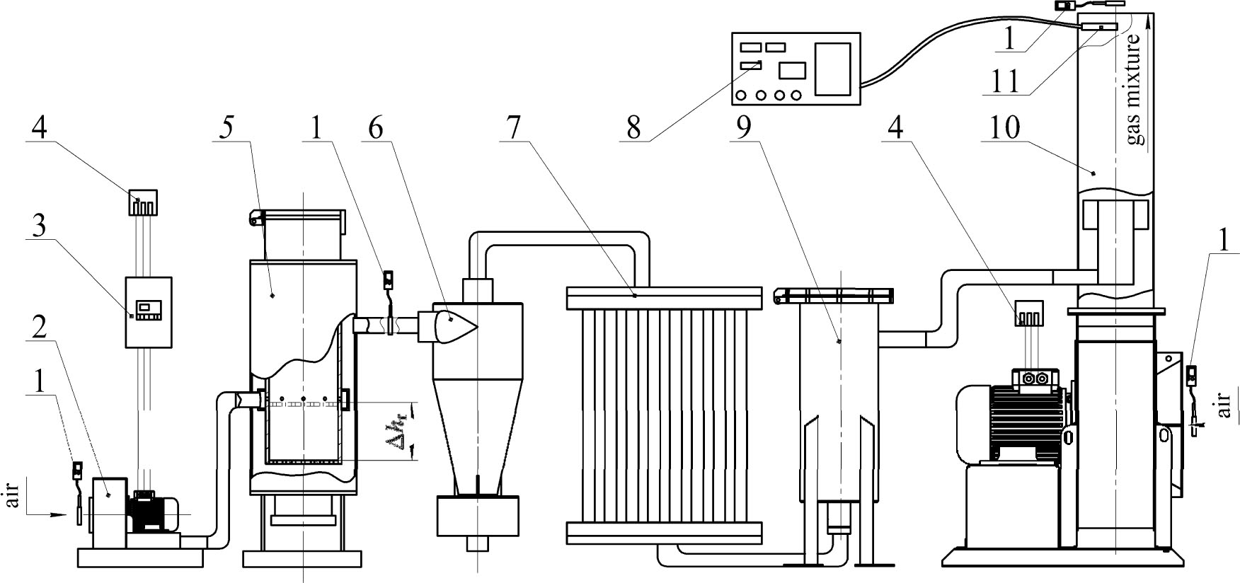
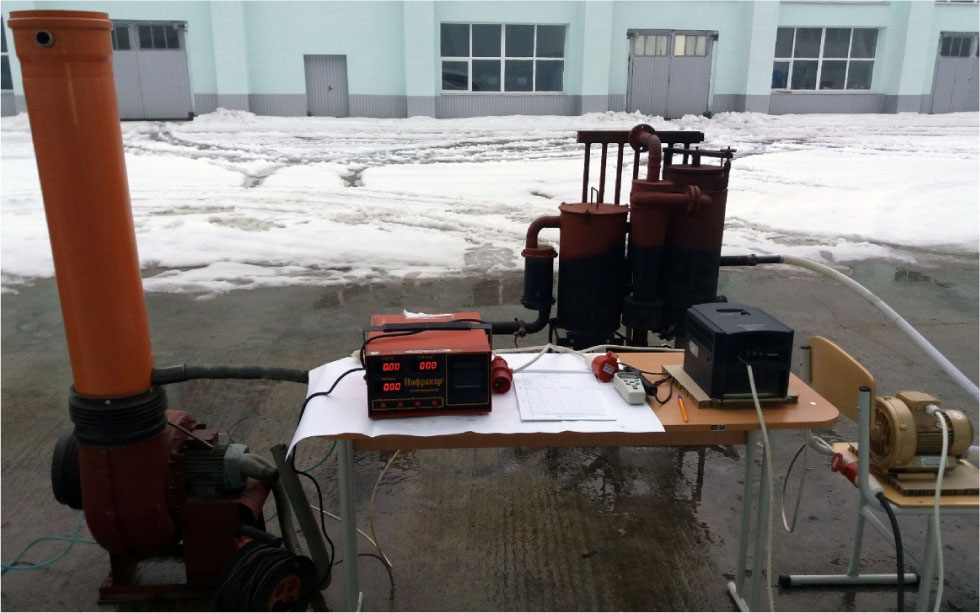
The air introduction into the gasifier is provided with an air blower (Figure 1, item 2), is used to control the air flow rate into the gasifier. The air speed at the inlet pipe of the gasifier was measured by the anemometer. General view of the experimental plant is shown in Figure 2.
General view of the experimental plant
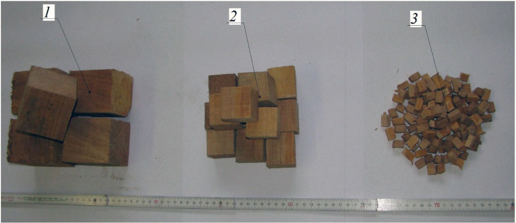
In relation to the geometrical properties of the biomass fuel, uniform cubical shape with three different sizes of side 10 mm, 40 mm and 70 mm were used (see Figure 3).
Particles geometry of fuel wood (side and surface area to the volume ratio): 1. 70 mm and 0.0857 mm−1, 2. 40 mm and 0.15 mm−1, 3. 10 mm and 0.6 mm−1
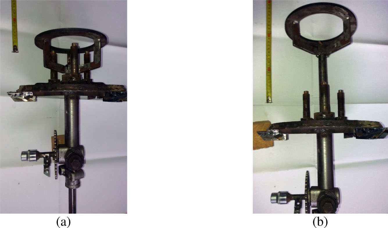
The gasifier grate was moved along the axis of the recovery zone by means of a special device, as shown in Figure 4, allowing changing the recovery zone height in the range from 5 mm to 151 mm. Recovery zone diameter was 200 mm.
The device for changing the recovery zone height: lower position (corresponds to the recovery zone height of 151 mm) (a) and upper position (corresponds to the recovery zone height of 5 mm) (b)
For measuring the concentration of CO a gas analyzer (Infrakar-M2T) was used with a measuring range of 0 to 7% CO concentration. Since the measurement range of the gas analyzer used was insufficient, it was necessary to reduce the concentration of CO within certain limits. For this purpose, a mixing arrangement (Figure 1, item 10) was used, ensuring efficient mixing of producer gas from the gasifier and the air that was introduced from the surrounding environment with the help of a centrifugal air intake fan.
The actual values of CO concentration in producer gas were calculated by the formula:
The intervals of values and variation levels of the investigated factors are given in Table 1. For the present research study the D-optimal Box-Behnken experiment design methodology is used.
The intervals of values and variation levels of the factors studied in the gasifier testing
Factor names |
Dimension |
Marking |
−1 |
Factor levels 0 |
+1 |
Variation intervals |
|---|---|---|---|---|---|---|
Particle size |
[mm] |
lf |
10 |
40 |
70 |
30 |
The air introduction into the gasifier |
[m3/s] |
qg |
0.00088 |
0.00628 |
0.01168 |
0.0054 |
The recovery zone height |
[mm] |
hr |
5 |
78 |
151 |
73 |
Assessment of the heterogeneity of variance of the experimental data was evaluated by Cochran criterion, the significance of regression equation coefficients was estimated by Student criterion, the adequacy of the obtained regression equation was evaluated by the Fisher criterion.
The results CO volumetric concentration measurements are shown in Table 2.
The values of given and measured variables
N |
Particle size (lf) [mm] |
Air introduction into the gasifier (qg) [m3/s] |
Recovery zone height (hr) [mm] |
CO concentration (nCO) [% by volume] |
|---|---|---|---|---|
1 |
70 |
0.01168 |
78 |
8.38 |
2 |
10 |
0.00088 |
78 |
8.66 |
3 |
70 |
0.00088 |
78 |
4.33 |
4 |
10 |
0.01168 |
78 |
27.49 |
5 |
70 |
0.00628 |
151 |
4.31 |
6 |
10 |
0.00628 |
5 |
4.92 |
7 |
70 |
0.00628 |
5 |
2.46 |
8 |
10 |
0.00628 |
151 |
15.38 |
9 |
40 |
0.01168 |
151 |
19.45 |
10 |
40 |
0.00088 |
5 |
0.00 |
11 |
40 |
0.01168 |
5 |
2.35 |
12 |
40 |
0.00088 |
151 |
8.66 |
13 |
40 |
0.00628 |
78 |
12.92 |
14 |
40 |
0.00628 |
78 |
12.80 |
15 |
40 |
0.00628 |
78 |
13.02 |
The Cochran criterion amounted to G = 0.112 and was less than its table value GT = 0.335 at a confidence level of 95%. This indicates the heterogeneity of variance of the experimental data. The Fisher criterion at a confidence level of 95%, amounted to F = 2.38 and was less than its table value FT = 2.53, indicating the adequacy of the regression equation obtained.
Based on the experimental data analysis, namely of the influence of the linear fuel particle sizes (lf), the air introduction into the gasifier (qg) and the recovery zone height (hr) on the CO concentration in producer gas (nCO), the following empirical mathematical dependence was obtained:
Graphical experimental dependence of the change of CO concentration on the particle size as a function of the air introduction into the gasifier is shown in Figure 5.
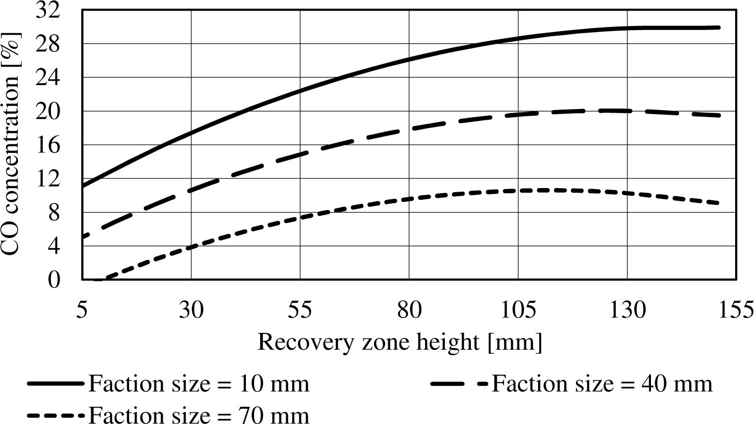
The dependence of the CO concentration on the faction size at the recovery zone height of 78 mm
In terms of reduction of the linear particle size, CO concentration in producer gas increases and reaches its maximum value 27% at the size of 10 mm. Scientific explanation of this: an increase of the total contact area of coal, located in the recovery zone with CO2 entering from the recovery zone. And as a consequence - the more intense the recovery reaction proceeds. The further reduction in the linear particle size is undesirable due to the design features of the operation of producer gas gasifier as the fuel with the smaller particle composition will spill through the holes of the grate, while reducing the size of the grate holes causing clogging and a sharp decrease in capacity relative to the air introduction into the gasifier recovery zone. In the study [18] it is also confirmed the increase in the CO concentration from 20 to 25% when using the fuel particle size of 30...50 mm when compared to the fuel particle of 100...150 mm.
Unlike most studies, for example [18], [19], the impact of the volumetric air introduction, not of its velocity, on the CO concentration was estimated. With increasing air supply, the CO concentration in producer gas increases (Figure 6), and with decreasing raw material particle size the increase in concentration is more intense. The increase in air introduction 0.0012 m3/s above maximum values of the experiment is difficult due to the gasifier design features, namely the danger of reaching a temperature of thermal destruction of the gasifier housing.
The dependence of the CO concentration on the air introduction at the recovery zone height of 78 mm
We also obtained the dependencies of the CO concentration on the recovery zone height at the minimum, average and maximum air introduction (Figures 7, 8, 9).
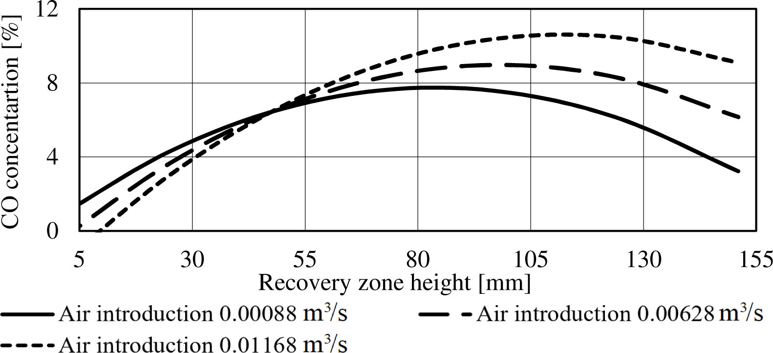
The dependence of the CO concentration on the recovery zone height at the minimum air introduction −0.00088 m3∕s
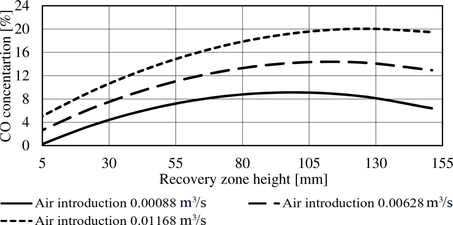
The dependence of the CO concentration on the recovery zone height with an average value of air introduction − 0.00628 m3/s
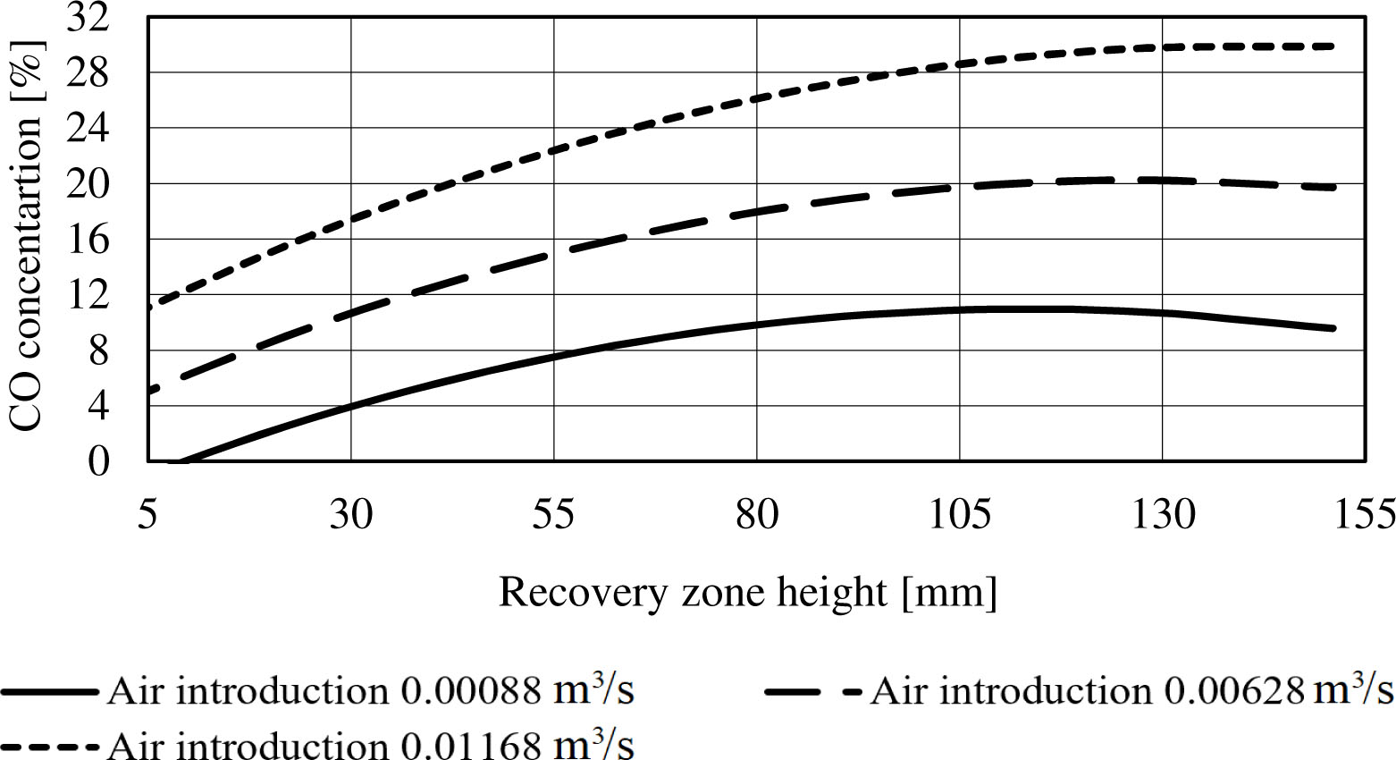
The dependence of the CO concentration on the recovery zone height at the maximum value of air introduction − 0.01168 m3/s
At the minimum air introduction 0.00088 m3/s the optimal values of the recovery zone height were as follows: particle size of 10 mm - from 105 to 130 mm, particle size of 40 mm – from 100 to 125 mm, and particle size of 70 mm – from 55 to 105 mm.
With an average air introduction 0.00628 m3/s, the optimal values of the recovery zone height were as follows: particle size of 10 mm – from 125 to 140 mm, particle size of 40 mm – from 105 to 130 mm, and for the particle size of 70 mm – from 80 to 125 mm.
At the maximum air introduction 0.01168 m3/s, the optimal values of the recovery zone height were as follows: particle size of 10 mm – from 130 to 150 mm, particle size of 40 mm - from 110 to 135 mm, and for the particle size of 70 mm – from 100 to 125 mm.
Dependencies of the CO concentration on the recovery zone height with the minimum, average and maximum fuel particle size are shown in Figures 10, 11 and 12.
The dependence of the CO concentration on the recovery zone height at the minimum value of fuel particle size − 10 mm
The dependence of the CO concentration on the recovery zone height at the average fuel particle size − 40 mm
The dependence of the CO concentration of the recovery zone height at the maximum value of the fuel particle size −70 mm
At the minimum value of the particle size 10 mm the optimal values of the recovery zone height were as follows: for the minimum air introduction – from 105 to 130 mm, for the average air introduction – from 125 to 150 mm, and for the maximum air introduction – from 130 to 150 mm.
At the average particle size 40 mm, the optimal values of the recovery zone height were as follows: for the minimum air introduction – from 100 to 105 mm, for the average air introduction - from 105 to 130 mm, and for the maximum air introduction - from 135 to 145 mm.
At the maximum value of the particle size 70 mm, the optimal values of the recovery zone height were as follows: for the minimum air introduction – from 75 to 90 mm, for the average air introduction – from 100 to 110 mm, and for the maximum air introduction – from 105 to 135 mm.
Thus, the optimum of the recovery zone height is determined by the air introduction into the gasifier and the fuel particle size. The air introduction into the gasifier and the amount of fuel particle size determines the gas speed through the recovery zone. Reducing the concentration of CO at excessive increase of the recovery zone height is the result of the deterioration of the carbon availability for the CO recovery. When the recovery zone height is increased the carbon concentration in the lower part of the recovery zone is decreased. It also decreases its availability to participate in the recovery reaction. At the recovery zone end we have almost ashes. The overestimated height of the recovery zone only creates additional resistance to the passage of gas. There is also a lowering the temperature in the lower part of the recovery zone and increasing the general aerodynamic resistance of the recovery zone.
On the basis of experimental data an equation was obtained that allows setting the optimal value of the height to diameter ratio of the recovery zone (hr/dr) ensuring the maximum CO concentration depending on the surface area to the volume ratio (SVR) and equivalence ratio of air introduction into the gasifier (ER):
This equation is graphically shown in Figure 13. As a result of experimental studies of the influence of linear sizes of fuel particles (lf), the air introduction into the gasifier (qg) and the recovery zone height hr on the CO concentration in combustible gas (nCO) they were determined the optimal values of the recovery zone height. Optimal height provid the maximum CO concentration at various values of the fuel particle size and air introduction into the gasifier which are described by eq. (3), composed on the basis of experimental studies.
The dependence of the optimal values of the height to diameter ratio of the recovery zone on the surface area to the volume ratio and equivalence ratio of air introduction into the gasifier
The obtained concentrations of CO in producer gas in compliance with the optimal values of the recovery zone height are in the range from 14 to 29.9%, which corresponds to CO concentrations obtained in the studies [15], [19], [20] and others. The optimal values of the height to diameter ratio of the recovery zone obtained in the result of the research lie in the range from 0.27 to 0.78 which generally corresponds to a height of the recovery zone with optimal temperature regime obtained in the studies [18], [21].
In case of insufficient recovery zone height the process of gasification is not complete. At excessive increase of recovery zone height, there is reduction of the temperature in the lower part of the recovery zone and increase of the aerodynamic resistance of the recovery zone. This leads to reducing the content of CO in producer gas and induces the need to establish an optimal value of the recovery zone height. The optimum of the recovery zone height is determined by the air introduction into the gasifier and the fuel particle size, since these parameters determine the speed of gas passing through the recovery zone. In this case, the fuel particle size influences the formation of the material porosity in the recovery zone on which the velocity of the gas in the recovery zone also depends.
In terms of reduction in the linear particle size, the CO concentration in producer gas increased and reached its maximum value of 29.9% at the particle size of 10 mm (surface area to the volume ratio of 0.6 mm−1). Herewith, the height to diameter ratio of the recovery zone was 0.75, and the air introduction − 0.01169 m3∕s (equivalence ratio ER = 0.34). With increasing air introduction, the CO concentration in producer gas increases and in terms of decreasing the particle size of raw materials the increase in concentration is more intense. The optimal values of the height to diameter ratio of the recovery zone are in the range from 0.27 to 0.78 and are described by empirical dependence on the particle size and the equivalence ratio of air introduction into the gasifier working zone. The further experimental research should be directed to finding the opportunities for gasification of wood and straw pellets mixture.
- ,
Benefits of Low Carbon Development Strategies in Emerging Cities of Developing Country: A Case of Kathmandu ,Journal of Sustainable Development of Energy, Water and Environment Systems , Vol. 4 (2), :141-1602016, https://doi.org/10.13044/j.sdewes.2016.04.0012 - ,
Integrated Use of Bioenergy Conversion Technologies in Agroecosystems ,INMATEH - Agricultural Engineering , Vol. 51 (1), :93-1002017 - ,
Biomass Gasification Models for Downdraft Gasifier: A State-of-the-art Review ,Renewable and Sustainable Energy Reviews , Vol. 50 , :583-5932015, https://doi.org/10.1016/j.rser.2015.05.012 - ,
The Research of Downdraft Gas Producer Heat Productivity on Straw ,Proceedings of International symposium “ISB-INMA TEH Agricultural and Mechanical Engineering” , 83-912016, October 27-29 - ,
Pre-processing of Sugarcane Bagasse for Gasification in a Downdraft Biomass Gasifier System: A Comprehensive Review ,Renewable and Sustainable Energy Reviews , Vol. 66 , :775-8012016, https://doi.org/10.1016/j.rser.2016.08.046 - ,
Small-scale Downdraft Gasifiers for Biomass Gasification: A Review ,Renewable and Sustainable Energy Reviews , Vol. 76 , :989-10032017, https://doi.org/10.1016/j.rser.2017.03.112 - ,
Experimental Studies on Producer Gas Generation from Wood Waste in a Downdraft Biomass Gasifier ,Bioresource Technology , Vol. 100 (12), :3127-31332009, https://doi.org/10.1016/j.biortech.2009.01.024 - ,
Thermodynamic Modeling of an Integrated Biomass Gasification and Solid Oxide Fuel Cell System ,Renewable Energy , Vol. 81 , :400-4102015, https://doi.org/10.1016/j.renene.2015.03.030 - ,
Three Zone Equilibrium and Kinetic Free Modeling of Biomass Gasifier - A Novel Approach ,Renewable Energy , Vol. 34 (4), :1050-10582009, https://doi.org/10.1016/j.renene.2008.08.001 - ,
Updraft Gasifier and ORC System for High Ash Content Biomass: A Modelling and Simulation Study ,Fuel Processing Technology , Vol. 156 , :394-4062016, https://doi.org/10.1016/j.fuproc.2016.09.031 - ,
Modeling and Simulation of a Downdraft Biomass Gasifier 1. Model Development and Validation ,Energy Conversion and Management , Vol. 52 (2), :1386-13962011, https://doi.org/10.1016/j.enconman.2010.10.001 - ,
Thermochemical Equilibrium Modelling of a Gasifying Process ,Energy Conversion and Management , Vol. 48 (1), :56-672007, https://doi.org/10.1016/j.enconman.2006.05.004 - ,
Prediction of Performance of a Downdraft Gasifier Using Equilibrium Modeling for Different Biomass Materials ,Energy Conversion and Management , Vol. 42 (12), :1499-15152001, https://doi.org/10.1016/S0196-8904(00)00078-9 - ,
Tri-generation System Based on Municipal Waste Gasification, Fuel Cell and an Absorption Chiller ,Journal of Sustainable Development of Energy, Water and Environment Systems , Vol. 6 (1), :13-322018, https://doi.org/10.13044/j.sdewes.d5.0172 - ,
Biomass Gasification for Combined Heat and Power Generation in the Cuban Context: Energetic and Economic Analysis ,Applied Thermal Engineering , Vol. 90 , :1-122015, https://doi.org/10.1016/j.applthermaleng.2015.06.095 - ,
Model-Based Downdraft Biomass Gasifier Operation and Design for Synthetic Gas Production ,Journal of Cleaner Production , Vol. 178 , :476-4932018, https://doi.org/10.1016/j.jclepro.2018.01.009 - ,
Co-gasification of Coal and Biomass Wastes in an Entrained Flow Gasifier: Modelling, Simulation and Integration Opportunities ,Journal of Natural Gas Science & Engineering , Vol. 37 , :126-1372016, https://doi.org/10.1016/j.jngse.2016.11.044 - ,
An Integrated Kinetic Model for Downdraft Gasifier Based on a Novel Approach that Optimises the Reduction Zone of Gasifier ,Biomass and Bioenergy , Vol. 109 , :172-1812018, https://doi.org/10.1016/j.biombioe.2017.12.030 - ,
Design and Development of Downdraft Gasifier to Generate Producer Gas ,Energy Procedia , Vol. 90 , :423-4312016, https://doi.org/10.1016/j.egypro.2016.11.209 - ,
Effects of Operating Parameters on Performance of a Downdraft Gasifier in Steady and Transient State ,Energy Conversion and Management , Vol. 155 , :138-1462018, https://doi.org/10.1016/j.enconman.2017.10.072 - ,
Integrated Downdraft Gasification with Power Generation System and Gasification Bottom Ash Reutilization for Clean Waste-to-energy and Resource Recovery System ,Journal of Cleaner Production , Vol. 188 , :69-792018, https://doi.org/10.1016/j.jclepro.2018.03.287