In recent decades, significant technological advancements in control systems, electronics, and material science have culminated in the creation of lightweight, cost-efficient multirotor Unmanned Aerial Vehicles (UAVs). These developments include sophisticated flight controllers, high-density power electric motors, batteries capable of rapid discharge, integrated inertial sensors, precise global positioning systems, advanced digital imaging technologies, and others, which are all adaptable for use in multirotor platforms.
Specifically, heavy lift multirotor UAVs, engineered for the transportation of substantial payloads, incorporate features such as water-resistant motors, propellers optimized for heavy-duty performance, high-capacity payload systems, robust and resilient structural designs with foldable arms, and extended operational endurance.
In practical applications, these UAVs have found extensive commercial use across various areas. Their roles cover aerial surveillance for inspection and surveying purposes, terrain mapping, cinematic aerial photography, infrastructural and pipeline inspections, railway monitoring, inspection of communication networks, and oversight of solar and wind energy installations. Additionally, they play an important role in agricultural applications, such as crop spraying and monitoring, delivery of healthcare necessities, and the transportation of goods and mail, especially to remote or inaccessible areas. This broad spectrum of applications underscores the versatility and essential role of heavy-lift multirotor UAVs in contemporary industry and service sectors. Figure 1 illustrates examples of commercially available units, while Table 1 provides detailed specifications. However, these multirotor UAVs face challenges related to their limited endurance and flight range, factors intricately linked to their take-off mass and onboard energy capacity. Typically, fully electric quadrotors, relying on electrochemical batteries (commonly Lithium polymer, LiPo), exhibit flight autonomy within the range of 15 to 30 minutes, with exceptional cases reaching up to 60 minutes [1], [2]
To address these constraints in endurance and range associated with battery power units (BPU), there is potential for exploration in hybrid power units (HPU). HPU systems leverage a combination of two or more power sources, such as an Internal Combustion Engine (ICE) coupled with an electricity generator (EG) [1], [2], or power sources based on hydrogen fuel cells (FC) and others [3], [4]. These approaches open avenues for extending the capabilities of multirotor UAVs.
In the context of this research, energy density implies the quantity of energy contained within a given volume of fuel, while specific energy signifies the amount of energy stored per unit mass of fuel. Fuels characterized by high energy density and specific energy are exceedingly advantageous for a wide array of applications, encompassing transportation, power generation, and aerospace engineering. It is crucial to emphasize that the selection of propellant fuel hinges greatly on the precise requisites of the application.
Examples of commercial heavy lift multirotor UAVs: Vulcan UAV D7 series [5] (a); Freefly systems ALTA X [6] (b); DJI Spreading Wings S1000 [7] (c)

Commercial heavy lift multirotor UAV specifications
| Model | Config. | Airframe diameter [mm] | Propeller size [inches]* | Power source (battery) | Flight autonomy | Approx. cost [Euros] |
|---|---|---|---|---|---|---|
| Vulcan UAV D7 series | Coax. octocopter | Approx. 1400 | 28 | 10s – 12s LiPo | No payload: 40 min; 10 kg: 20 min |
40000 |
| Freefly systems ALTA X | Flat quadcopter | Approx. 1414 | 33 | 12s LiPo | No payload: 40 min; 9 kg: 25 min |
17000 |
| DJI Spreading Wings S1000 | Flat octocopter | Approx. 1045 | 15 | 6s LiPo | 5.3 kg: 15 min | 4000 |
1 inch = 25.4 mm
For instance, although gasoline and diesel exhibit superior energy densities and specific energies, they are also linked to heightened emissions of detrimental pollutants, rendering them unsuitable for environmentally sensitive applications. Consequently, it becomes imperative to consider an assortment of factors, including energy density, specific energy, environmental ramifications, and safety when deliberating upon propellant fuels for a given purpose. Progress in fuel technology persistently propels advancements in energy density, specific energy, and emissions control, thereby furnishing enhanced adaptability and distinct applications.
In Figure 2a comprehensive snapshot of energy density and specific energy levels for a collection of propellant fuels, encompassing notable options like petrol, diesel, propane, and others is shown as orientation [8].
Energy densities of various energy storage materials and technologies [8]
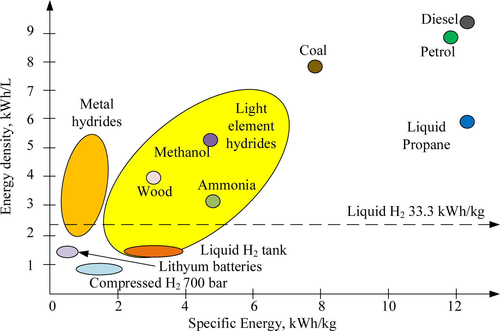
Nowadays, LiPo batteries, for instance, exhibit a specific energy of approximately 0.25 kWh/kg, while fuel cells demonstrate higher specific energy values of up to 1 kWh/kg [9]. However, it is noteworthy that ICE-based power systems present a unique advantage courtesy of the remarkable specific energy density of gasoline fuel, which stands at approximately 12.88 kWh/kg [10].
In the quest to evaluate the feasibility of the HPU featuring both an ICE and an EG, a comprehensive assessment entails an examination of the efficiency of each component. The efficiency of an ICE in highly theorised and idealized assumptions can be up to 67% according to [11], but it is inherently bound by factors such as the compression ratio and adiabatic ratio coefficient. In real-world applications, practical efficiencies are typically around 0.3 [12], influenced by numerous factors, including engine type and operational conditions. It is important to emphasize that the selection of an efficiency value of 0.2 was deliberate, aiming to uphold a highly conservative assessment to mitigate potential overshoot errors in total energy assessment.
For the HPU, the Electric Generator (EG) is commonly of the Brushless Direct Current (BLDC) type, where the average efficiency was validated experimentally in [1], [2]. and typically ranges between 0.7 and 0.9.
Hence, it is possible to approximate the specific energy for a hybrid electric power unit through the following relation:
(1)
Upon scaling adjustments, accounting for factors such as the engine’s thermal efficiency, and mechanical losses, and utilizing the conservative estimate of electrical machine (generator) efficiency, it becomes evident, as illustrated in Figure 2, that the achieved energy density of the ICE–EG hybrid power unit surpasses that of batteries (significantly) and fuel cell power units.
Based on a review of research activities within this field, it is evident that the issue of aircraft autonomy is a subject of active investigation. Additionally, advanced propulsion systems are currently the focus of ongoing research efforts. Typically, hybrid propulsion research is oriented towards fixed-wing aircraft, while multirotor aircraft are primarily configured with fully electric propulsion systems. While there are occurrences of multirotor aircraft employing fuel cells and similar energy sources, such instances are relatively infrequent within the broader context of multirotor propulsion technologies.
References [1], [2] establish the foundational framework for modelling, designing control systems, and validating experiments related to the HPU comprising an ICE-EG configuration and are used as the basis for this research.
Reference [3] introduces a comprehensive model designed to assess the performance of a fuel cell hybrid system integrated into a multirotor drone. This model serves as a valuable tool for evaluating the feasibility of employing a hybrid fuel cell system for a specific drone and ascertaining whether it offers superior endurance compared to conventional batteries.
In a practical case study, the utilization of a fuel cell hybrid system is observed to enhance flight duration by a notable 76% when contrasted with the prevalent LiPo batteries. Additionally, this versatile model lends itself to the optimization of system configurations and sensitivity analysis, facilitating further advancements in performance.
It is worth noting, however, that the current cost of implementing a fuel cell hybrid system stands at approximately twelve times that of LiPo batteries. Moreover, there exists a threshold energy system mass of 7.3 kg, beyond which the fuel cell hybrid system demonstrates a performance advantage over batteries in terms of endurance.
Reference [4] investigates the integration of a hybrid power system into a compact UAV. The analysis draws upon data obtained from rigorous bench tests and sophisticated simulations. Notably, the hybrid power system leads to a substantial enhancement in the UAV’s flight performance, extending its endurance from 470 to an impressive 970 minutes. This research study highlights the practicality of hybrid power systems for small UAVs and also establishes the effectiveness of renewable energy sources for mobile applications.
In their review article [13], the authors conducted a systematic review of the literature on hybrid-powered multi-rotor UAVs. They emphasized the importance of internal ICE and highlighted the necessity for further advancements in FCs and batteries. Additionally, they emphasized the significance of high-power powertrains in extending UAV endurance and payload capabilities, suggesting the evaluation of reliable performance parameters across various power ranges. It is found that the pivotal role of hybrid power systems in enhancing UAV capabilities is urged for continued development and optimization. Finally, they proposed future research to effectively integrate multiple power sources, enabling better control and management of generated power while storing excess energy.
Reference [14] introduces a prototype of an advanced hybrid generator employing innovative electronics and a supercapacitor array. This design aims to enhance efficiency, prevent overheating, and extend the operational lifespan of engines within unmanned aerial systems. The system incorporates a throttle control mechanism, and the prototype boasts nearly twice the power output when compared to conventional hybrid generators. Control of the system is managed through a field-programmable gate array (FPGA), which includes dedicated control loops for individual components, along with a comprehensive monitoring and data transmission system for real-time data collection.
The study of fuel cell-based power sources has emerged as a promising path to significantly extend the flight endurance of industrial multirotor drones, surpassing the limitations posed by contemporary lithium-based batteries [15]. While commercially accessible lightweight alternatives exist, embracing this technology presents a set of hurdles, encompassing certification, technical enhancements, and operational intricacies.
The prospect of liquid-cooled fuel cells holds promise in broadening the flight capabilities of UAVs, yet the inherent challenge lies in mitigating the elevated system mass they introduce. Conquering obstacles related to hydrogen storage and substantiating the technology’s operational and financial advantages under real-world conditions stands as a fundamental step in its widespread adoption.
In the domain of multirotor propulsion systems, reference [16] offers an introductory overview, complemented by empirical characterizations. Simultaneously, reference [17] outlines a method for selecting propulsion components based on simplified modelling and introduces an online validation software tool tailored for preliminary calculations during the initial phases of aircraft design.
As shown by reference [18], electrochemical batteries stand out as the predominant power source for multirotor UAVs. This paper conducts a thorough analysis of power consumption and presents an endurance estimation model tailored for aircraft powered by LiPo batteries. Furthermore, a series of experimental flight tests conducted using a commercial multirotor platform confirm the theoretical analysis therein.
In reference [19], the authors propose a conceptual solution for the design of heavy-lift multirotor systems. Their comprehensive analysis encompasses five distinct series of electric propulsion units, each characterized by different multirotor configurations. The study presents results for payloads ranging from 10 kg up to a substantial 100 kg.
Reference [20] shifts the focus to the practical implementation of a hybrid-electric power system, validated through simulations. The results, while indicating the potential for enhanced flight endurance in fixed-wing aircraft, also highlight several details associated with small Internal Combustion Engines (ICEs), including challenges such as intense vibrations and the necessity of active cooling or alternative thermal management solutions.
The reference [21] thoroughly explores the domain of ICE-based propulsion, comprehensively covering the static and dynamic characteristics of these propulsion systems in a valuable manner.
In the study [22] the authors assess challenges in UAV technology, including limited flight duration and payload capacity, focusing on Hybrid Power Systems. The study conducts a systematic literature review for such systems in multi-rotor UAVs and analyzes available commercial models of such systems.
In their study [23], the authors adopted a novel methodology, utilizing fast-response electric motors for stability and integrating a gasoline propulsion system for lift force in their exploration of the impact of a gasoline-electric hybrid multirotor drone on flight duration relative to an electric multirotor drone. While this approach exhibits potential, additional testing is required to validate its effectiveness and feasibility for practical applications.
In summary, the research studies discussed in these references offer valuable insights into the design, modelling, and characterization of multirotor propulsion systems and power sources. The knowledge gleaned from these sources can improve the development of propulsion systems that exhibit greater effectiveness for multirotor UAVs, particularly in the realm of heavy-lift applications.
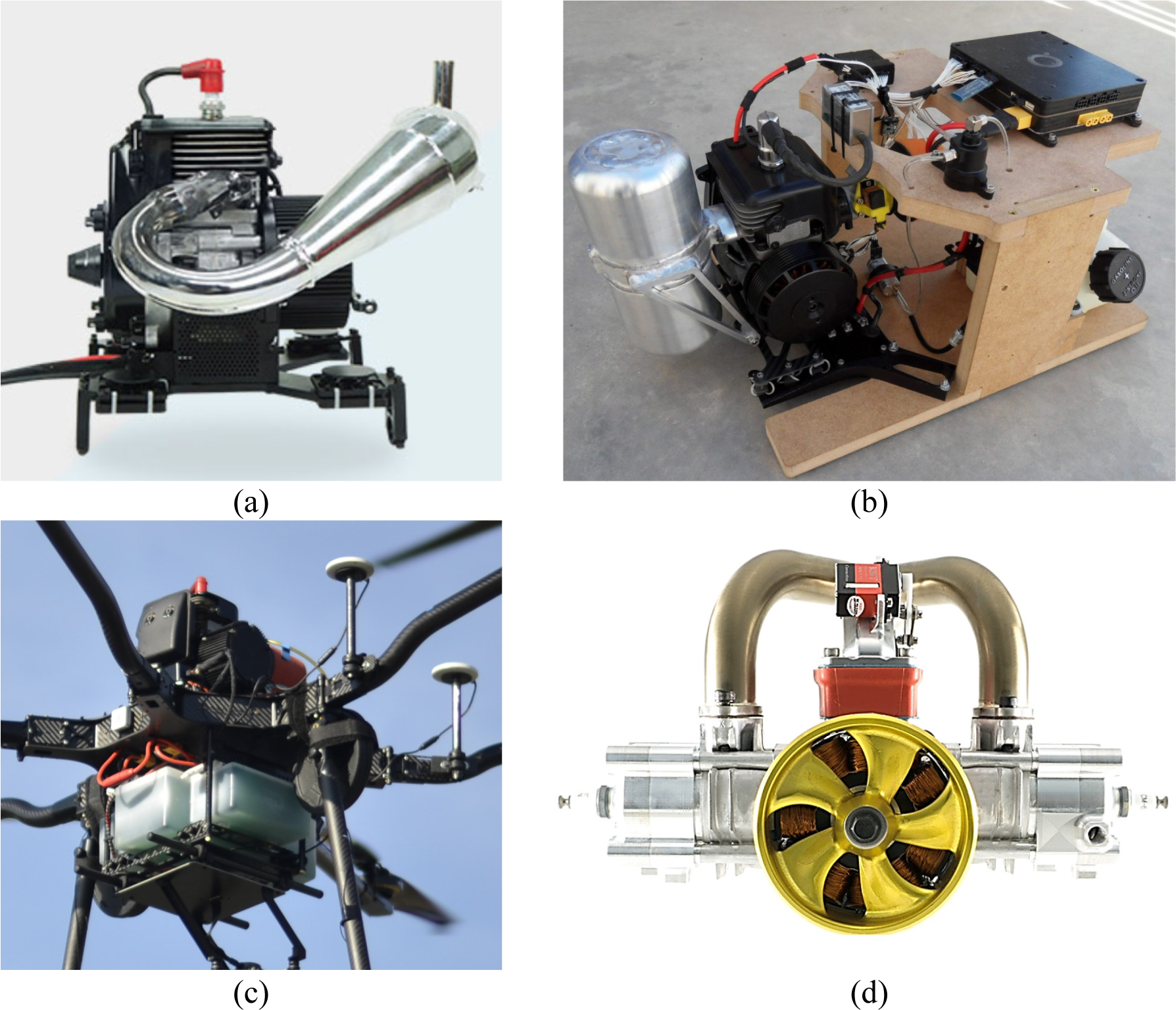
Currently, the market for HPU is in its early stage of development, however, several notable products have emerged in the hybrid power market. For instance, FoxtechFPV™, a Chinese manufacturer, offers the GAIA™ multirotor, utilizing the NOVA2400™ HPU, depicted in Figure 3a. This system boasts a continuous power capacity of 2400 W, can accommodate a maximum take-off mass of 23 kg, and is priced at approximately 5000 EUR.
Another noteworthy player is Quaternium, a Spanish manufacturer, which manufactures the HYBRIX 2.1™ featuring an advertised power output of 2600 W and a maximum take-off mass of 25 kg, as illustrated in Figure 3b. This product is available in the price range of 5000 EUR to 8000 EUR and has achieved a world record for flight endurance, with over 10 hours and 10 minutes of hovering time.
Additionally, Aerocámaras, a Spanish manufacturer, offers the AEROHYB™ hex copter, powered by the NOVA2400™. It is advertised to support a maximum take-off mass of 19 kg and provides a flight time of up to two hours with a maximum payload, as shown in Figure 3c.
Lastly, Pegasus Aeronautics, a Canadian company, introduces the GE70™ hybrid generator, which utilizes a two-stroke boxer engine from model planes. This generator boasts a maximum power output of 4000 W, incorporates liquid cooling, and fuel injection, and is priced at around 15000 EUR, as depicted in Figure 3d. Additional information regarding these solutions and similar approaches can be found in references [14], [22].
Commercial hybrid power units: (a) Foxtech NOVA2400 [24]; (b) Quaternium HYBRIX 2.1 [25]; (c) Aerocámaras AEROHYB [26]; (d) Pegasus Aeronautics GE70 [27]
This section outlines the mathematical representations and equations used to characterize different aspects of multirotor UAVs, focusing primarily on their mass, thrust, power consumption, endurance, and energy sources. It details how parameters such as total mass, thrust, power consumption, and energy capacity are calculated and modelled, considering factors like propulsion systems (battery or hybrid), payload, and operational conditions. This framework serves as a basis for analysing and comparing the performance of different multirotor configurations and power units.
First, it is fundamental to understand the interplay among mass, thrust, and payload capacity to accurately estimate the necessary propulsion power for a multirotor. The formula to calculate the mass of the multirotor is given as follows.
(2)
In the above equation, mUAV stands for the mass of the multirotor which includes the combined weight of the frame, motors and speed controllers, propellers, electronics, and any other onboard equipment (excluding the power unit). Meanwhile, mPU is the total mass of the power unit, encompassing elements such as batteries or a hybrid power unit with fuel. Lastly, mPL represents the mass of the useful payload, which could be items like a camera, agricultural spraying unit, or other similar devices installed on the multirotor.
Next, it is important to consider the hovering condition, which is reached when the total onboard weight is balanced by the collective thrust produced by all the propellers.
(3)
Ftotal represents the combined thrust of all propellers, and FT,i represents i-th individual thrust contribution of i-th propeller.
The above expression is applicable only under ideal steady-state conditions, where external disturbances such as aerodynamic drag, varying wind conditions, or any transient forces are absent. In real-world scenarios, these factors can significantly influence the multirotor performance, necessitating additional considerations in the design and control algorithms to maintain stability and efficiency.
When evaluating two different power systems for multirotors, we introduce a simplification and assume a consistent mass for the multirotor in all tests. This assumption suggests that while executing the same complex movement, i.e. following a set trajectory, the system would consume the same amount of energy for each case, regarding the power source type – with the condition of the same take-off mass. With this premise, the analysis can be streamlined to primarily focus on the hovering state which, in turn, significantly reduces the complexity of the model.
In evaluating multirotor performance, endurance and flight range are usually most key factors. Endurance is defined as the multirotor flight duration capability, while flight range indicates the distance it can traverse on a single charge or fuel load. These metrics are typically inversely related, with enhancements in one often resulting in compromises in the other. Maximum endurance is usually achieved at lower flight speeds, where most of the energy is allocated to counteracting the multirotor weight, thus leaving minimal energy for propulsion. This, however, limits the flight range due to reduced speed. For analytical convenience, this study focuses on comparing the performance of different power units (battery versus hybrid power units) based on hovering endurance, excluding transient effects. This approach provides a valid assessment of the power unit’s efficiency, encapsulated by the following equation.
(4)
Ea is the available energy, Pi is power consumption, and te is the endurance.
LiPo (Lithium Polymer) batteries are the preferred power source for multirotor UAVs, valued for their high energy density and rapid discharge capability. Yet, they present challenges including degradation over time, diminished performance in cold conditions, and a discharge rate-dependent capacity. Detailed experimental characterizations of LiPo batteries are available in the literature [1], [2].
Typically, the nominal voltage range for LiPo batteries, from fully charged (100% state of charge) to fully depleted (0% state of charge), spans from 4.2 to 3.3 volts, measured in an open circuit voltage state post chemical stabilization.
It is well-known that electrochemical batteries exhibit non-linear behaviour during charging and discharging, resulting in an exceptionally complex simulation model. For this study, the analysis has been conducted to develop a straightforward discharge model.
For that purpose, the cell voltage, Vref is assumed to be a constant 3.75 V and the depth of discharge, ηDOD is set at 80%, as a practical value for maintaining battery longevity. The battery charge capacity Qb is derived from the manufacturer’s specifications. The energy capacity of the LiPo battery is then calculated as follows.
(5)
The hybrid power unit topology considered in this study is based on previous work [1], [2] and depicted in Figure 4. This unit comprises an ICE, an EG with an integrated rectifier and filter (RF), and an auxiliary LiPo battery. These components are connected to a direct current (DC) power bus.
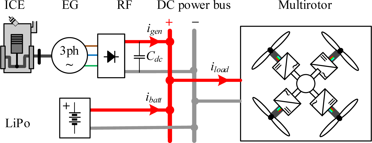
The ICE serves as the primary mover, mechanically linked to the electricity generator, such as a Permanent Magnet Synchronous Motor (PMSM) or Brushless DC (BLDC) machine. The power generated by the ICE-EG set acts as the main power supply, catering to the quasi-steady-state power requirements, particularly for maintaining hover.
For peak load demands, such as during intense movements that cause a sudden spike in electrical load over a brief period, the battery connection is employed for peak load shaving. This setup allows the hybrid system to smoothly manage power surges until the power output stabilizes. Furthermore, in the event of an ICE-EG system failure, the auxiliary LiPo battery can provide emergency power for several minutes, enabling the emergency landing.
Constraints are introduced to reduce the number of variables in the analysis to keep enough generalities:
ICE drives the electricity generator (BLDC machine), which provides for a quasi-steady–state load power supply, and mass reduction due to fuel consumption is neglected
the battery unit is used for peak load shaving and emergency landing; the battery cannot be charged in flight.
The available energy from the Internal Combustion Engine-Electric Generator (ICE-EG) set is contingent upon several factors: the continuous output power, denoted as PICE,EG, the onboard volume of the fuel Vtank, and the average fuel consumption rate Qfuel.
Considering that the typical operational regime for such ICE-EG units is near its maximum torque output, it is a reasonable approximation to assume a constant rate of fuel consumption.
However, it is important to note that fuel consumption is intricately linked to the operational conditions of the unit. A more exhaustive evaluation, particularly when the engine is operated across its full throttle range, would necessitate a detailed analysis of potential variations in fuel consumption rates. To estimate the available energy from the ICE-EG set, the following equation can be utilized as follows.
(6)
The total energy capacity of the hybrid power unit under review is quantified as the aggregate of the effective energy derived from the Internal Combustion Engine-Electric Generator (ICE-EG) set and the energy stored in the auxiliary battery as follows.
(7)
When initiating this study, a crucial step involved the selection of three distinct propulsion systems, each comprising motor-ESC-propeller sets, as illustrated in Figure 5. These sets are instrumental in conceptualizing three hypothetical multirotor configurations tailored for medium to heavy lift operations. Notably, the propulsion units selected for this study are based on components the authors have acquired and utilized in constructing multiple UAVs, providing a good representation of heavy-lift multirotor capabilities.
Considered propulsion sets[29]: Xrotor X6 (a); Xrotor X8 (b); Xrotor X9 (c).
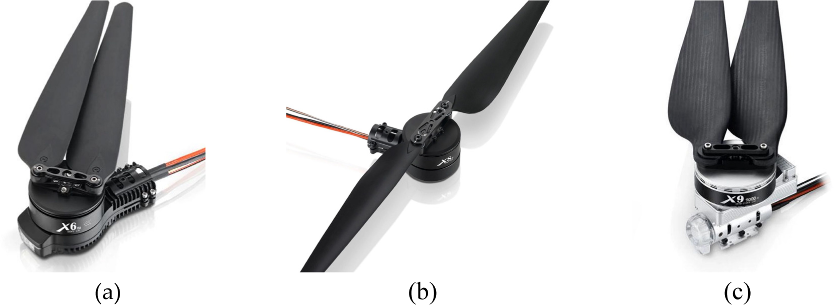
Each chosen propulsion system is designed for a high-voltage operation, utilizing 12-cell Lithium Polymer batteries that deliver a nominal voltage of 44.4 volts. The BLDC motors, as integral to these propulsion sets, are characterized by a low voltage constant (KV < 200). This feature translates into lower propeller speeds but higher torques, making these systems particularly adept at handling heavier payloads, which is a defining requirement for medium to heavy-lift multirotors.
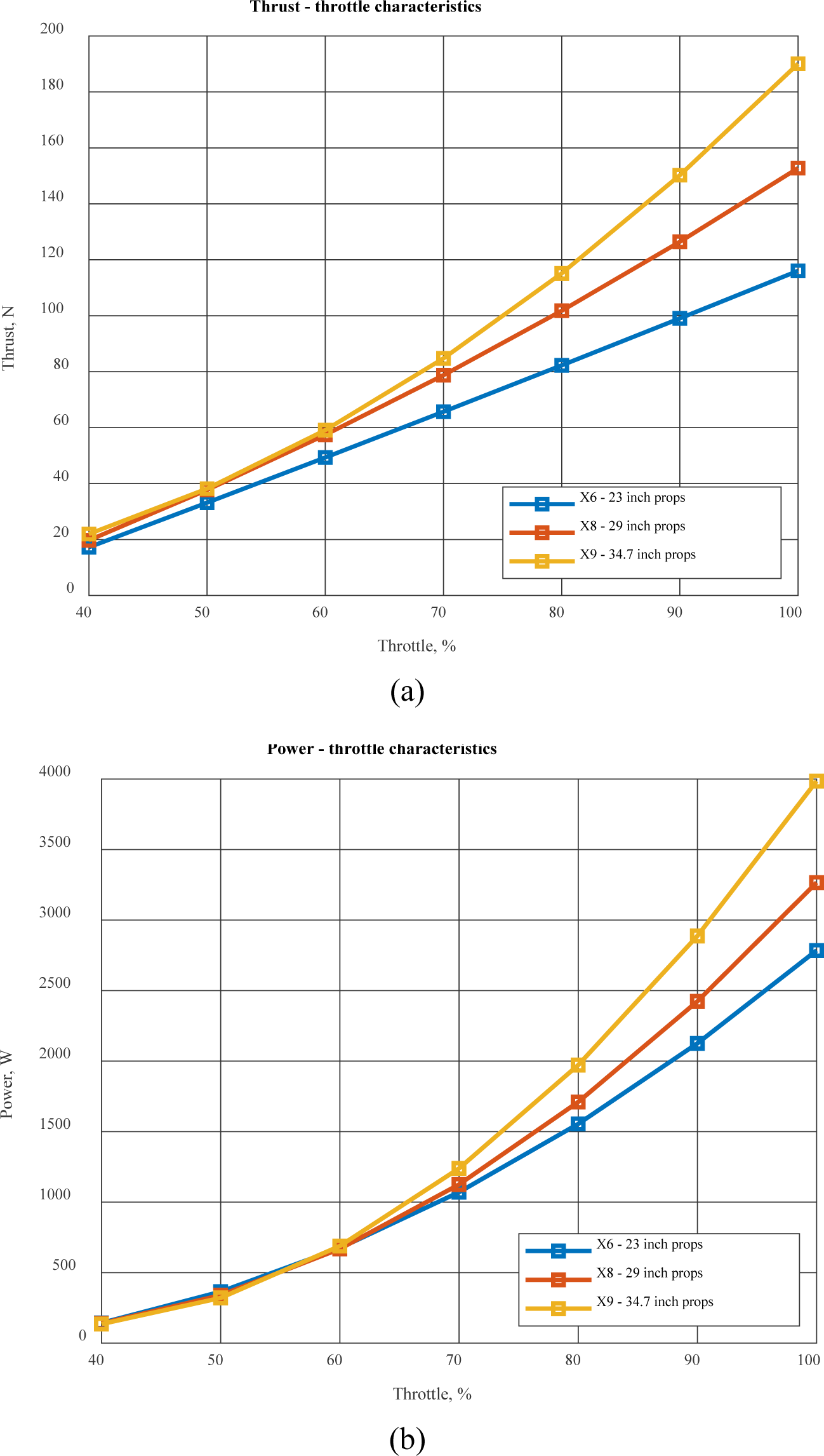
The specifications of the selected propulsion sets are presented in Table 2 and Figure 6, providing detailed information on the motor and propeller sizes, as well as the electrical and mechanical characteristics of the ESCs. The data presented in the table and figure is used as a basis for the subsequent analysis and comparison of the multirotor designs.
By selecting these specific propulsions, the authors aim to create hypothetical designs that represent typical medium to heavy-lift multirotors commonly used in various applications such as aerial photography, surveying, and cargo delivery.
Considered propulsion specifications
| Case No. | Propulsion unit designation | Propeller size [inches]* | Recommended load per axis [kg] | Battery cells configuration | ESC const. and peak Current [A] | Motor KV [rpm/V] | Single unit mass [g] |
|---|---|---|---|---|---|---|---|
| 1 | Xrotor Pro X6™ | 23 | 3 – 5 | 6S – 12S | 80, 100 | 180 | 720 |
| 2 | Xrotor Pro X8™ | 29 | 5 – 7 | 6S – 12S | 80, 100 | 100 | 1040 |
| 3 | Xrotor Pro X9™ | 34.7 | 7 – 9.5 | 6S – 12S | 120, 150 | 110 | 1400 |
1 inch = 25.4 mm
For the sake of this study, commercially available high-voltage (12S) LiPo batteries with varying capacities were chosen for detailed analysis, as outlined in Table 3 [30], [31] and [32]. It’s a common practice to connect batteries in parallel to increase overall capacity, but it is crucial to ensure that their specifications, particularly internal resistance, are closely matched to guarantee balanced load sharing.
According to the equations previously established, the total available energy for each battery type was calculated. This step is fundamental in assessing the potential performance and endurance of the various multirotor configurations under consideration.
Considered battery packs
| Case No. | Battery designation | Capacity [Ah] | Mass [kg] | Nominal energy [Wh] |
|---|---|---|---|---|
| 1 | Gens Ace 5 Ah 44.4V | 5 | 1.49 | 180 |
| 2 | Okcell 8 Ah 44.4V | 8 | 2.20 | 288 |
| 3 | Tattu 10 Ah 44.4V | 10 | 2.74 | 360 |
| 4 | Tattu Plus 16 Ah 44.4 V | 16 | 4.25 | 576 |
| 5 | Tattu Plus 22 Ah 44.4V | 22 | 6.06 | 792 |
| 6 | 2 x Tattu Plus 22 Ah 44.4V | 44 | 12.12 | 1584 |
| 7 | 3 x Tattu Plus 22 Ah 44.4V | 66 | 18.17 | 2376 |
| 8 | 4 x Tattu Plus 22 Ah 44.4V | 88 | 24.23 | 3168 |
Characterisation of selected propulsion systems: thrust vs throttle (a); power consumption vs throttle (b)
Selecting an appropriate ICE requires careful consideration of various factors, including:
Continuous and peak power capabilities,
Fuel consumption rate,
Overall mass and size of the engine.
In this study, a case analysis was conducted using commercially available ICEs that align well with the defined propulsion requirements. The selected engines are coupled with compatible electric generators, with their masses obtained directly from the manufacturers’ specifications. Additionally, an auxiliary battery was chosen for each setup, designed to provide emergency power in the event of a Hybrid Power Unit (HPU) failure, thus mitigating the risk of multirotor loss.
Furthermore, the mass of the requisite rectifying electronics was evaluated, allowing for the calculation of the total mass of each propulsion unit. The total available power output was then estimated based on the maximum power rating of the ICE and an assumed utility factor for energy conversion of 0.7, a value derived from previous measurements, cited in [1], [2] and discussed in the introductory section of this paper.
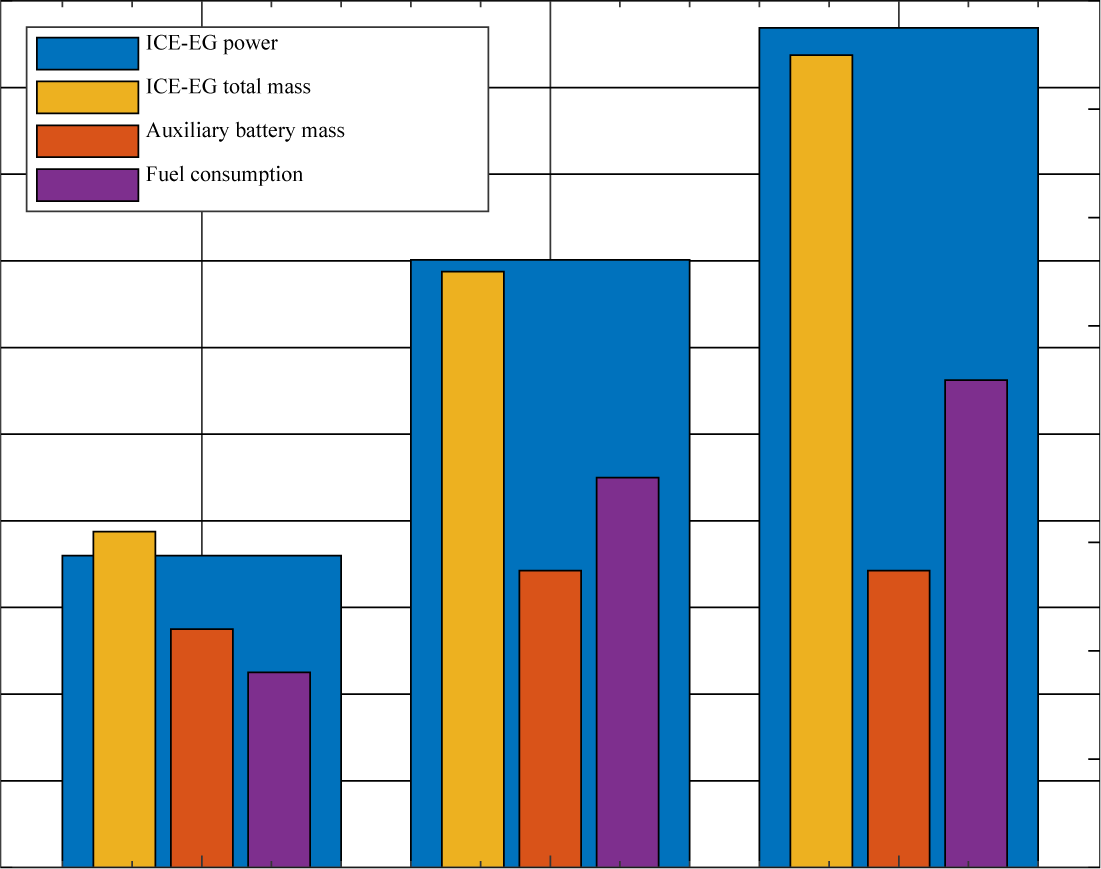
Detailed specifications of the ICEs, electric generators, and auxiliary batteries, along with their respective masses and power outputs, are provided in Table 4 and illustrated in Figure 7. This comprehensive data set forms the basis for a thorough assessment of the potential performance and efficiency of these hybrid propulsion systems.
Considered hybrid power unit specifications
| Case No. | Engine mass [kg] | Displacement [cm³] | Engine power [W] | Fuel consumption [L/h] | |
|---|---|---|---|---|---|
| 1 | 2.3 | 32 | 2400 | 1.8 | |
| 2 | 4 | 70 | 4675 | 2.8 | |
| 3 | 5 | 100 | 6460 | 4.5 | |
| Case No. | Generator mass [kg] | Rectifier mass [kg] | Auxiliary battery charge capacity [Wh] | Full dry mass of HPU [kg] | Estimated available power (after losses) [W] |
| 1 | 0.6 | 0.2 | 8 | 3.1 | 1800 |
| 2 | 1.2 | 0.3 | 10 | 5.5 | 3506.25 |
| 3 | 2 | 0.5 | 16 | 7.5 | 4845 |
Characterisation of the selected ICE-EG hybrid power units, case 1 based on Zenoah G320™, case 2 based on Desert Aircraft DA-70™ and case 3 based on Desert Aircraft DA-100™
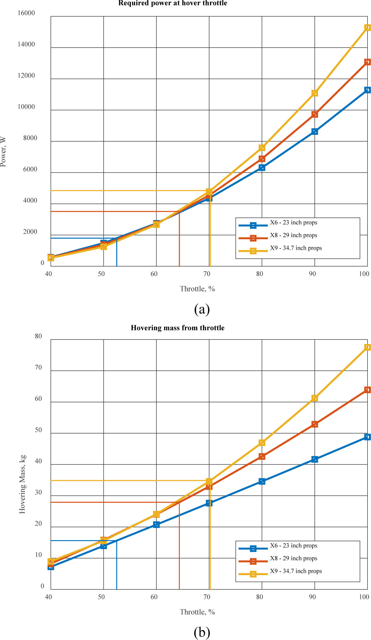
In this study, a key constraint applied is the take-off mass, which is governed by the power output capabilities of the hybrid ICE-EG set. This constraint facilitates a methodical comparison between purely battery-operated power units and hybrid power systems. To determine the maximum take-off mass for each multirotor configuration, we rely on the propulsion characteristics available, ensuring that this mass remains consistent regardless of the power unit type.
The methodology for ascertaining the maximum take-off mass involves several steps, as outlined in Figure 8 and Table 5. Initially, the power required for hovering is calculated for the hybrid ICE-EG set, based on data from the manufacturer. Subsequently, the maximum take-off mass is derived, considering both this hovering power requirement and that of a solely battery-powered unit. The lower of the two resulting values is then adopted as the maximum take-off mass.
Case quadrotor parameters: (a) power vs throttle; (b) hover mass vs throttle
Considered battery packs
| Propulsion unit designation | Available power from HPU (for hovering case) | Hover case at throttle [%] | Overall take-off mass [kg] |
|---|---|---|---|
| XRotor Pro X6 | 1800 | 52 | 15.6 |
| XRotor Pro X8 | 3506 | 64 | 27.9 |
| XRotor Pro X9 | 4845 | 70 | 34.9 |
Following the determination of the maximum take-off mass, it is required to ascertain the maximum payload capacity for each multirotor design. This capacity is calculated by deducting the weight of the multirotor, inclusive of its power unit, from the maximum take-off mass.
To summarize, the study imposes a take-off mass constraint linked to the power output of the hybrid ICE-EG set.
This parameter is crucial in enabling an equitable comparison between battery-only and hybrid power units. Furthermore, the established maximum take-off mass serves as a foundational metric in defining the maximum payload capacity for each multirotor configuration.
The procedure has the following steps.
Find the value of the throttle on which the HPU available power is achieved, according to the obtained throttle value, find the available propulsion thrust.
Following the equations and methodology shown in the modelling section, a mass analysis of the multirotor designs was conducted, with the findings tabulated in Table 6. The masses of the propulsion units were ascertained from the manufacturers’ specifications. For the frame and avionics components, mass estimates were derived based on data from comparable commercial models.
It is imperative to highlight that, in each multirotor configuration, the take-off mass was maintained as a constant variable, while the aggregate mass of the power unit (PU) and payload was varied. This specific research design was chosen to explore the effects of these variations on the multirotors hovering endurance capability.
In essence, the mass analysis for the multirotor configurations was performed using a synthesis of data from manufacturers, existing market examples, and the author’s expertise. The primary aim of the study was to assess the impact of different PU and payload mass combinations on hovering endurance, under a fixed take-off mass constraint. The comprehensive results of this analysis are detailed in Table 6.
Quadrotor cases mass parameters
| Case No. | Propulsion unit mass [kg] | Frame mass [kg] | Avionics mass [kg] | Total quadrotor mass (Without power unit and payload) [kg] | Available PU + payload mass [kg] |
|---|---|---|---|---|---|
| 1 | 2.88 | 3.5 | 0.5 | 6.88 | 8.72 |
| 2 | 4.16 | 5 | 0.8 | 9.96 | 17.94 |
| 3 | 5.6 | 6.5 | 1 | 13.1 | 21.8 |
This section introduces three case studies that implement the models and parameters previously discussed. The initial case study centres on evaluating a purely electric power unit for each type of multirotor. This analysis unfolds through a series of methodical steps:
The initial step involves selecting a set of appropriate batteries that align with the maximum permissible take-off mass for each propulsion type.
Subsequently, the available energy of each selected battery is computed, adhering to the methodology delineated in the batteries section.
Lastly, the endurance for each battery is calculated using the formulas provided in the endurance section of the study.
The second case study involves the analysis of hybrid power units, which is conducted in the following steps:
The process begins by identifying appropriate fuel tanks, followed by calculating the total mass of the ICE-EG set combined with the fuel. This calculation ensures adherence to the maximum permissible take-off mass for each propulsion type.
For each selected fuel tank, the time duration to deplete the tank is determined based on the fuel consumption specifications provided in Table 4 and the capacities of the tanks.
Finally, the endurance of each HPU configuration, incorporating all suitable fuel tank scenarios, is calculated. This involves using the determined power requirements for hovering, along with the equations outlined in the hybrid power unit section of the study.
By executing these methodologies, we can effectively compare the performance of pure electric power units with hybrid power units, particularly in terms of endurance enhancement. These case studies are vital in revealing the endurance capabilities of multirotors under different power unit configurations. The comprehensive results of these analyses are detailed in the following sections.
This section outlines the analysis results of various power unit setups for multirotors, including mass breakdowns, endurance calculations, and comparisons between the pure battery and hybrid configurations. It covers findings on battery-powered multirotor designs, details on fuel tank selection and operational durations for hybrid units, and comparative analysis highlighting increased endurance with hybrid setups.
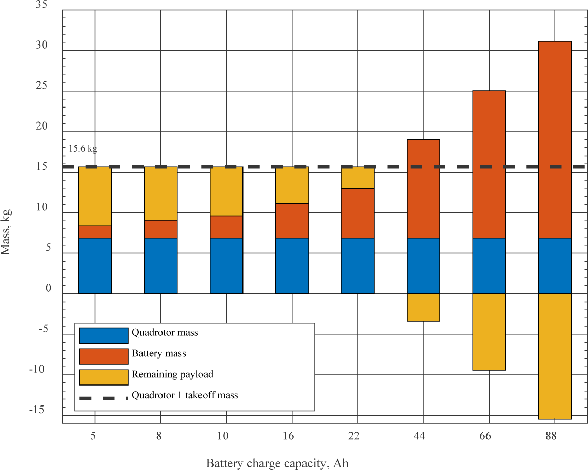
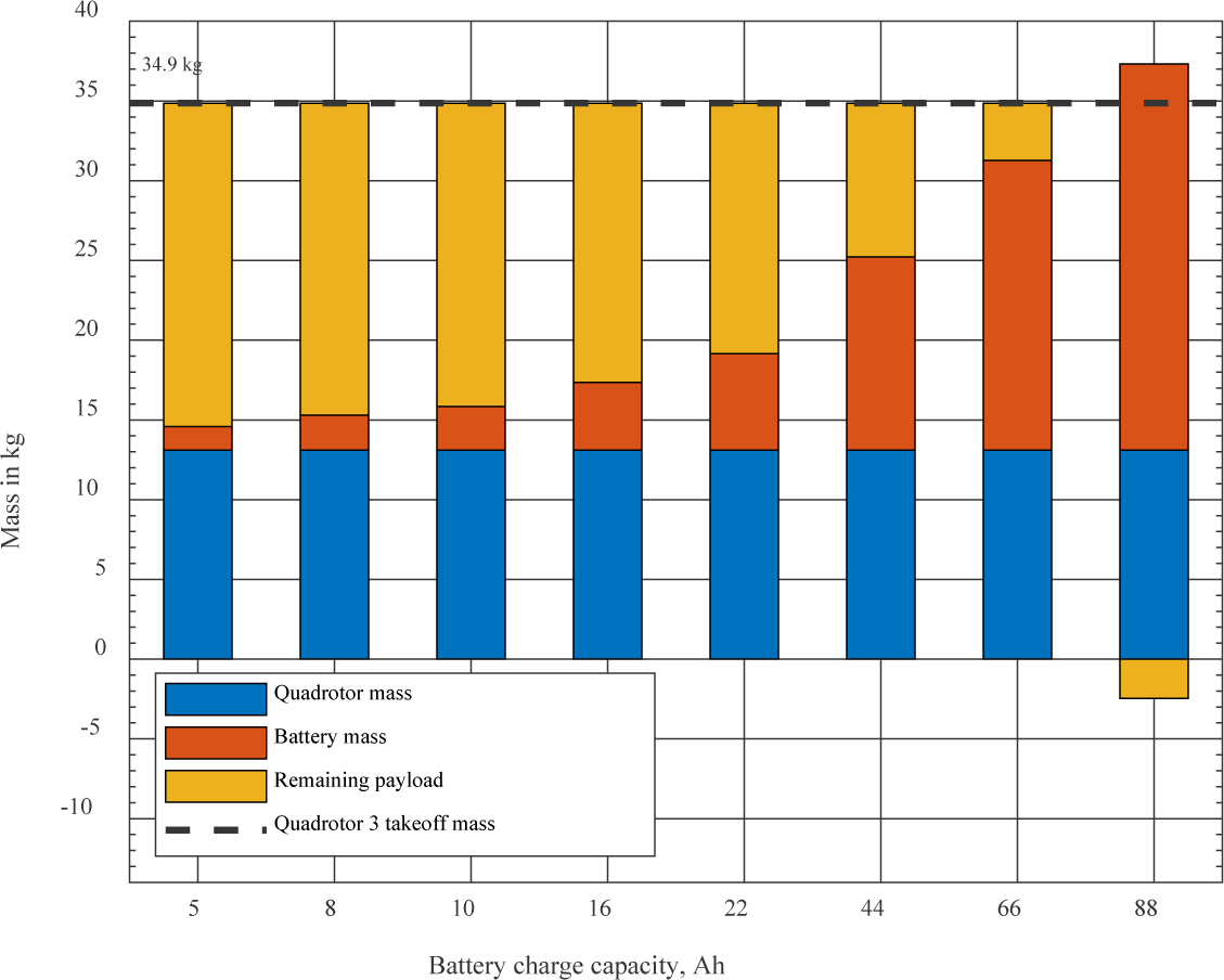
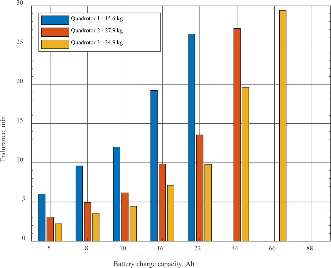
Following the methodology established in the preceding chapter, mass breakdown graphs for three multirotor designs are presented in Figure 9 to Figure 11. Scenarios, where the mass of the battery pack exceeded the specified hovering thrust capacity for each multirotor, were excluded from consideration. The calculated endurance for these designs is depicted in Figure 12.
Mass breakdown, battery-powered multirotor: case 1, based on Xrotor X6
Mass breakdown, battery-powered multirotor: case 2, based on Xrotor X8
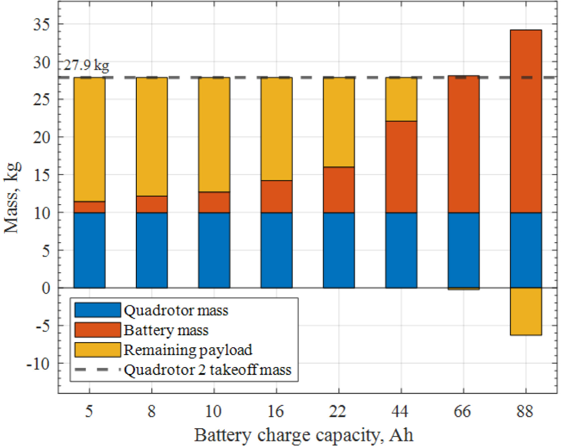
Mass breakdown, battery-powered multirotor: case 3, based on Xrotor X9
Calculated endurances per multirotor take-off mass
The previous section detailed our investigation into HPU, focusing on selecting suitable fuel tanks and calculating the total mass of the ICE-EG and fuel. This was done to ensure compliance with the maximum permissible take-off mass for each propulsion type. Here, we present the results of that analysis.
Following the steps outlined in the case study section, we undertook a tank analysis, calculating both the fuel mass and the overall mass of the full tanks for the selected options. Utilizing fuel consumption data from Table 4 and the capacities of these tanks, we determined the maximum operational duration for each full tank in various HPU and tank scenarios. The results of this analysis are compiled in Table 7.
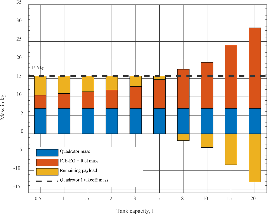
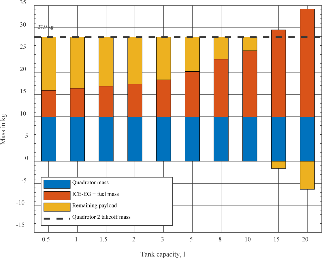
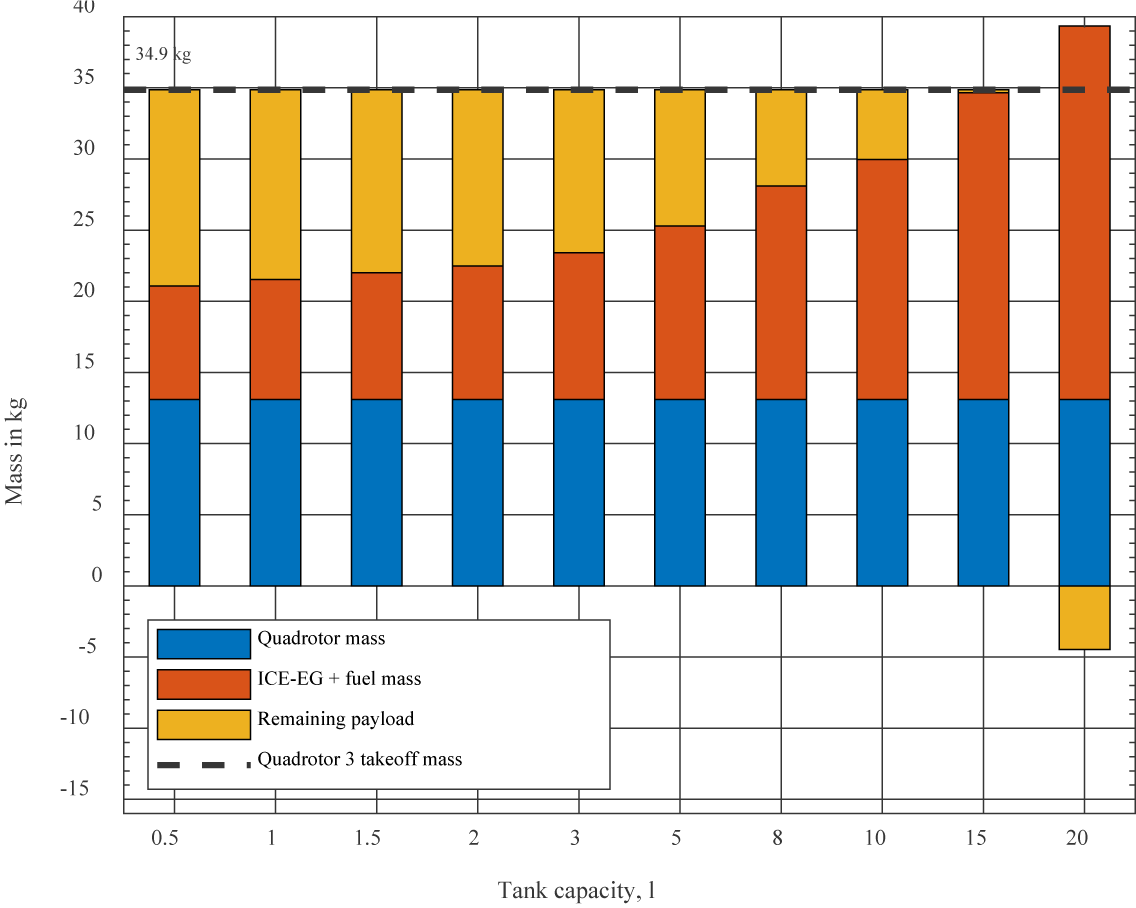
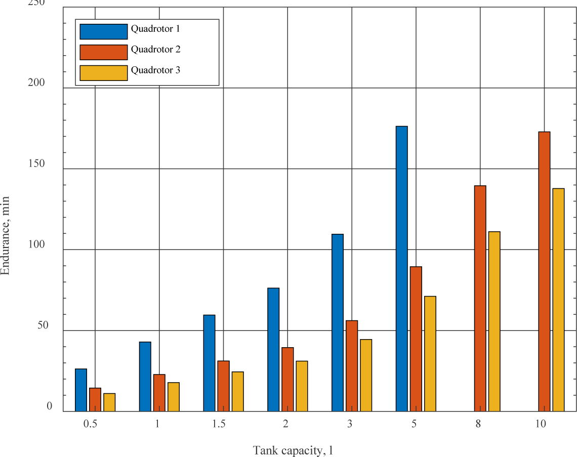
For a clearer interpretation of these findings, mass breakdown graphs for three multirotor designs are exhibited in Figure 13 to Figure 15. Configurations, where the HPU mass surpassed the designated hovering thrust for each multirotor, were excluded. Furthermore, Figure 16 showcases the calculated endurance for each HPU and tank combination.
These results are essential in assessing the practicality of hybrid power units for boosting multirotor endurance. They offer insights into the most effective tank configurations for each HPU and the upper limits of endurance achievable. When compared with the findings from the pure electric power unit analysis, these results help identify the most appropriate power unit configuration for specific multirotor designs.
Propulsion thrust and power consumption for considered configurations
| Tank capacity [L] | Tank mass [kg] | Fuel mass [kg] | Total mass [kg] | Quadrotor 1, endurance per tank [h] | Quadrotor 2, endurance per tank [h] | Quadrotor 3, endurance per tank [h] |
|---|---|---|---|---|---|---|
| 0,5 | 0.1 | 0.38 | 0.48 | 0.28 | 0.14 | 0.11 |
| 1 | 0.2 | 0.75 | 0.95 | 0.56 | 0.28 | 0.22 |
| 1.5 | 0.3 | 1.13 | 1.43 | 0.83 | 0.42 | 0.33 |
| 2 | 0.4 | 1.5 | 1.9 | 1.11 | 0.56 | 0.44 |
| 3 | 0.6 | 2.25 | 2.85 | 1.67 | 0.83 | 0.67 |
| 5 | 1 | 3.75 | 4.75 | 2.78 | 1.39 | 1.11 |
| 8 | 1.6 | 6 | 7.6 | 4.44 | 2.22 | 1.78 |
| 10 | 2 | 7.5 | 9.5 | 5.56 | 2.78 | 2.22 |
Mass breakdown, hybrid-powered multirotor: case 1, based on Xrotor X6
Mass breakdown, hybrid-powered multirotor: case 2, based on Xrotor X8
Mass breakdown, hybrid-powered multirotor: case 3, based on Xrotor X9
Calculated endurances per multirotor take-off mass
The findings from the preceding section indicate that a multirotors endurance is influenced by the configuration of its power unit and the amount of fuel it carries. In Figure 17a, the correlation between the total available energy and the mass of the power unit is depicted. This graph reveals that the energy available from hybrid power units substantially surpasses that of purely battery-powered units once the mass of the power unit surpasses a certain threshold. These critical mass values for the respective multirotor cases are identified as 4.94 kg, 8.41 kg, and 10.88 kg.
Additionally, Figure 17b illustrates a significant improvement in achieved endurance when the mass of the power unit exceeds these critical values. This trend underscores the superiority of hybrid power units in extending flight durations. The visual data presented in these figures provide a compelling argument for the advantages of hybrid systems in scenarios where extended endurance is a priority.
Endurance, energy, PU mass analysis: Endurance vs PU mass (a); Energy vs PU mass (b)
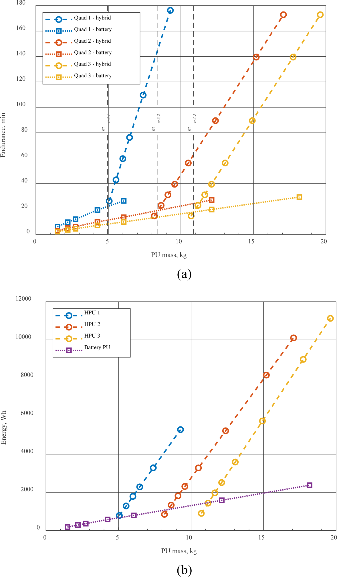
Figure 18 elucidates the relationship between the available payload capacity and the endurance achieved using various power unit configurations. The graph shows an increase in endurance as the mass of the power unit grows, up to a pivotal point. Beyond this critical value, the hybrid power unit begins to significantly outperform its battery-powered counterpart. This trend suggests that for multirotors tasked with carrying larger payloads or those with higher power demands, a hybrid power unit becomes a more effective choice for extending flight duration.
Endurance versus remaining payload mass, first multirotor case (a); Second multirotor case (b); Third multirotor case (c)
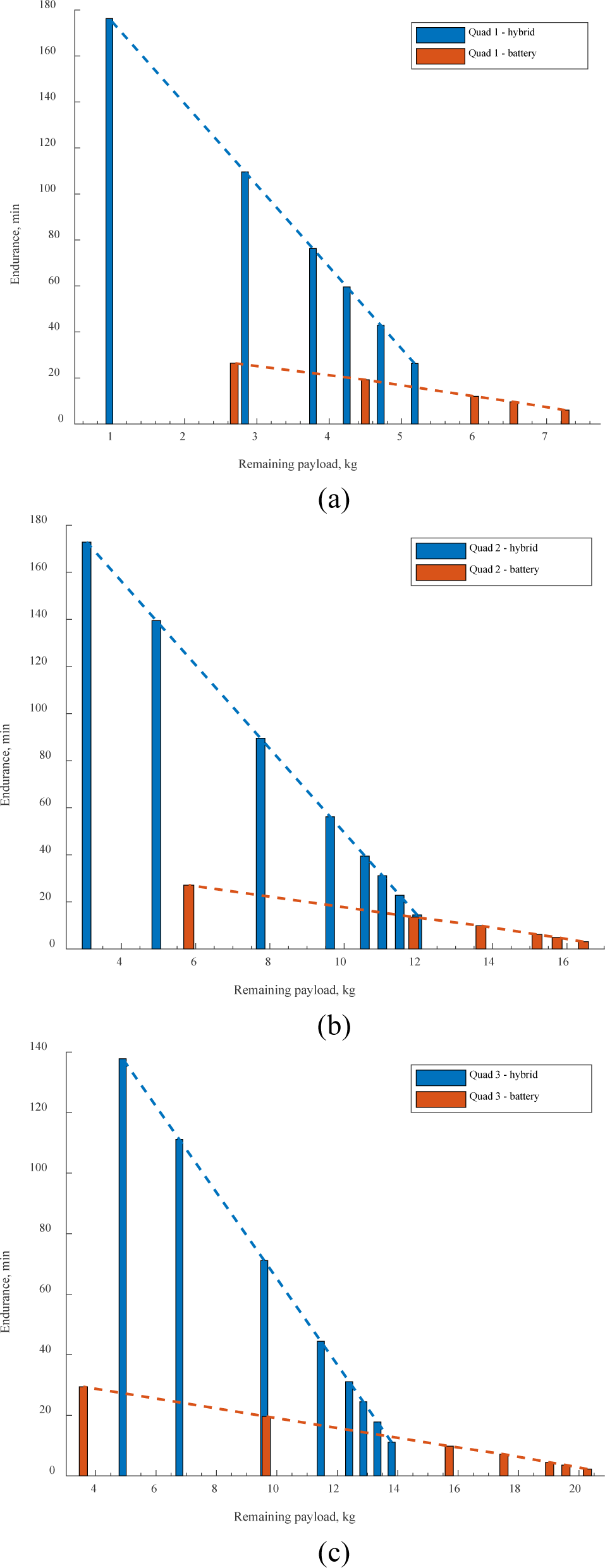
To summarize, the findings from this analysis offer valuable perspectives on the balance between the mass of the power unit, the endurance it can provide, and the payload capacity. For multirotors with modest power needs or smaller payloads, battery-powered units emerge as the preferable option. Conversely, in cases where the multirotor must meet higher power demands or carry larger payloads, the benefits of a hybrid power unit become more pronounced. The critical mass values identified for each multirotor scenario serve as a practical benchmark, guiding the selection of the most suitable power unit configuration to achieve the desired level of endurance.
In the final stage of our performance analysis, the goal is to assess how hybrid power units (HPU) stack up against battery power units (BPU) for each type of multirotor. For this purpose, an HPU with a mass equivalent to that of the multirotor is selected, along with a LiPo battery of comparable capacity – specifically, 22 Ah, 44 Ah, and 66 Ah for each respective case.
Data for the HPU is derived through linear interpolations, using the information from Figure 17 and Figure 18. Figure 17a displays the total available energy as a function of the power unit’s mass, while Figure 17b shows the connection between the power unit mass and the endurance achieved.
Conversely, Figure 18 illustrates how the endurance varies with the remaining payload capacity for different power units.
Applying this method revealed that for the three multirotor cases, the HPU offered an increase in endurance by 35, 57, and 118 minutes, respectively, compared to the BPU. These findings are detailed in Table 8.
This comparative analysis sheds light on the distinct performance capabilities of HPU and BPU in various scenarios. The results indicate that when the HPU’s mass surpasses a specific threshold, it surpasses the BPU in endurance. Such insights are crucial for designers in selecting the most appropriate power unit for a multirotor, considering its specific mass and payload requirements.
Propulsion thrust and power consumption for considered configurations – summary
| Multirotor case 1 -15.6 kg take-off mass, 6.06 kg PU mass | LiPo | Hybrid | Difference | |
| Effective energy | 792 Wh | 1857 Wh | + 1065 Wh | |
| Endurance | 26.4 min | 61.9 min | +35.5 min | |
| Multirotor case 2 -27.9 kg take-off mass, 12.12 kg PU mass | LiPo | Hybrid | Difference | |
| Effective energy, Wh | 1584 Wh | 4954 Wh | + 3370 Wh | |
| Endurance, min | 27.1 min | 84.8 min | + 57.7 min | |
| Multirotor case 3 -34.9 kg take-off mass, 18.17 kg PU mass | LiPo | Hybrid | Difference | |
| Effective energy, Wh | 2376 Wh | 9742 Wh | + 7366 Wh | |
| Endurance, min | 29.42 min | 147.2 min | + 117.78 min | |
The model introduced in this study presents a methodology for assessing the practicality of employing a hybrid ICE-electric power unit in multirotor UAVs. This analysis encompasses the selection of appropriate power units and batteries, and it delves into the characteristics of both hybrid and battery-only power systems. A key conclusion from this research is the evident superiority of hybrid power units vs batteries in terms of endurance. The study illustrates that, particularly beyond a certain critical mass threshold, hybrid systems can deliver endurance improvements ranging from double to quintuple that of traditional battery power units, depending on the fuel used.
This understanding of the hybrid ICE-Electric power unit’s feasibility for multirotor UAVs opens new avenues for designers. With the insights gathered from this research, designers now have the tools to evaluate hybrid power units as a competitive alternative to standard battery power units. They can apply the model detailed in this study to select the most suitable power unit and battery for each multirotor design and conduct comprehensive analyses of both hybrid and battery power systems.
Overall, the insights provided by this research can inform design decisions for multirotor UAVs, leading to the development of more efficient and effective designs. This, in turn, can contribute to the advancement of multirotor UAV technology, enabling new applications and use cases.
Looking ahead, future research could extend the proposed model to encompass the entire UAV system. This expansion would facilitate the planning and simulation of realistic flight trajectories, along with more accurate estimations of fuel consumption and power demand. Moreover, investigating the environmental impact of the ICE-EG power unit is another critical area for future study. Employing pollution assessment models to optimize engine performance and minimize emissions, such as using fuel injectors or catalytic converters, would be beneficial. Additionally, developing an acoustical model to evaluate the sound spectrum and loudness of the engine in decibels could further refine the design and operational aspects of these power units, enhancing their overall appeal and sustainability.
Author Contributions: Conceptualisation, methodology, investigation, MK, JB, DP; software, JB, MC; validation, MK, JB, DP; resources, data curation, DP, DB; writing—draft preparation, editing MK. All authors have read and agreed to the published version of the manuscript.
This research titled “Energy Management within the Unmanned Aerial Vehicle Hybrid Propulsion” was funded by the Adris Group Foundation Programme – Knowledge and Discoveries, 2021.
This research is supported by the European Union’s Horizon Europe research program Widening Participation and Spreading Excellence, through project Strengthening Research and Innovation Excellence in Autonomous Aerial Systems (AeroSTREAM) - Grant agreement ID: 101071270.
| E(ICE,EG) | Available energy from the ICE-EG set | [Wh] |
| ELiPo | Energy capacity of the LiPo battery | [Wh] |
| ELiPo,AUX | Energy capacity of the auxiliary LiPo battery | [Wh] |
| Ea | Available onboard energy | [kWh/kg] |
| Egasoline | Total energy of gasoline | [kWh/kg] |
| Etotal | Total energy of hybrid system | [kWh/kg] |
| Ftotal | Sum of all thrusts of the propellers | [N] |
| Pi | Current power consumption | [kW] |
| PICE,EG | Current power output of ICE-EG set | [kW] |
| Qb | Battery charge capacity | [Ah] |
| Qfuel | Average fuel consumption | [ml/min] |
| Vtank | Tank volume | [ml] |
| Vref | Constant cell voltage | [V] |
| mPL | kg, total mass of payload | [kg] |
| mPU | Total mass of power unit | [kg] |
| mUAV | Multirotor mass without a power unit | [kg] |
| mtotal | Total mass of aircraft | [kg] |
| te | Aircraft endurance | [h] |
| ηDOD | Depth of discharge constrain |
| ηEG | Energy efficiency of EG |
| ηICE | Energy efficiency of ICE |
- ,
Modeling, Controller Design and Simulation Groundwork on Multirotor Unmanned Aerial Vehicle Hybrid Power Unit ,Energies (Basel) , Vol. 14 (21),pp 7125 , 2021, https://doi.org/https://doi.org/10.3390/en14217125 - ,
Modeling, Control System Design and Preliminary Experimental Verification of a Hybrid Power Unit Suitable for Multirotor UAVs ,Energies (Basel) , Vol. 14 (9),pp 2669 , 2021, https://doi.org/https://doi.org/10.3390/en14092669 - ,
Suitability Analysis of Implementing a Fuel Cell on a Multirotor Drone ,Journal of Aerospace Technology and Management , (12), 2020, https://doi.org/https://doi.org/10.5028/jatm.v12.1172 - ,
Analysis of a hydrogen fuel cell-PV power system for small UAV ,Int J Hydrogen Energy , Vol. 41 (15),pp 6422–6432 , 2016, https://doi.org/https://doi.org/10.1016/j.ijhydene.2016.02.129 - , 2022, https://vulcanuav.com
- , 2022, https://freeflysystems.com/alta-x
- , 2022, https://www.dji.com/hr/spreading-wings-s1000
- ,
Hydrogen nexus in a sustainable energy future ,Energy Environ Sci , Vol. 1 (1),pp 79 , 2008, https://doi.org/https://doi.org/10.1039/b810104n - ,
Power Sources for Unmanned Aerial Vehicles: A State-of-the Art ,Applied Sciences , Vol. 13 (21),pp 11932 , 2023, https://doi.org/https://doi.org/10.3390/app132111932 - ,
Batteries: Higher energy density than gasoline? ,Energy Policy , Vol. 37 (7),pp 2639–2641 , 2009, https://doi.org/https://doi.org/10.1016/j.enpol.2009.02.030 - ,
Maximum efficiencies for internal combustion engines: Thermodynamic limitations ,International Journal of Engine Research , Vol. 19 (10),pp 1005–1023 , 2018, https://doi.org/https://doi.org/10.1177/1468087417737700 - ,
Improving Thermal Efficiency of Internal Combustion Engines: Recent Progress and Remaining Challenges ,Energies (Basel) , Vol. 15 (17),pp 6222 , 2022, https://doi.org/https://doi.org/10.3390/en15176222 - ,
Hybrid Power Systems in Multi-Rotor UAVs: A Scientific Research and Industrial Production Perspective ,IEEE Access , Vol. 11 ,pp 438–458 , 2023, https://doi.org/https://doi.org/10.1109/ACCESS.2022.3232958 - ,
Preliminary Results of a Hybrid Thermoelectric Propulsion System for a Multirotor UAS with Active Rectifying, Electronic Throttle Control and Supercapacitors ,Applied Sciences , Vol. 11 (17),pp 7899 , 2021, https://doi.org/https://doi.org/10.3390/app11177899 - , State-of-Technology and Barriers for Adoption of Fuel Cell Powered Multirotor Drones, 2020 International Conference on Unmanned Aircraft Systems (ICUAS), 2020
- ,
Method for Characterization of a Multirotor UAV Electric Propulsion System ,Applied Sciences , Vol. 10 (22),pp 8229 , 2020, https://doi.org/https://doi.org/10.3390/app10228229 - , Electric Multirotor UAV Propulsion System Sizing for Performance Prediction and Design Optimization, 2016
- , Power and endurance modelling of battery-powered rotorcraft, 2015 IEEE/RSJ International Conference on Intelligent Robots and Systems (IROS), 2015
- , Design Considerations for Autonomous Cargo Transportation Multirotor UAVs, 2021
- , Considerations for Pairing the IC Engine and Electric Motor in a Hybrid Power System for Small UAVs, 2018
- , Identification results of an internal combustion engine as a quadrotor propulsion system, 2017 25th Mediterranean Conference on Control and Automation (MED), 2017
- ,
Hybrid Power Systems in Multi-Rotor UAVs: A Scientific Research and Industrial Production Perspective ,IEEE Access , Vol. 11 ,pp 438–458 , 2023, https://doi.org/https://doi.org/10.1109/ACCESS.2022.3232958 - ,
Flight Time Optimization and Modeling of a Hybrid Gasoline–Electric Multirotor Drone: An Experimental Study ,Aerospace , Vol. 9 (12),pp 799 , 2022, https://doi.org/https://doi.org/10.3390/aerospace9120799 - , 2022, https://www.foxtechfpv.com/foxtech-nova-2400-generator.html
- , 2022, https://www.quaternium.com/range-extender
- , 2022, https://dronehibrido.com/en
- , 2022, https://www.pegasusaero.ca/ge70
- , Control System Design for Hybrid Power Supply of an Unmanned Aerial Vehicle Based on Linearized Averaged Process Models.
- , 2022, https://www.hobbywingdirect.com/collections/x-series
- , 2022, https://www.gensace.de/gens-ace-5000mah-44-4v-45c-12s1p-lipo-battery-pack.html
- , 2022, https://www.rc-wing.com/okcell-12s-44-4v-8000mah-20c-intelligent-battery-for-uav-drones.html
- , 2022, https://www.genstattu.com/12s-44-4v-lipo-battery.html


